

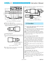


(1) RC connection example 1
¡
Remote ON / OFF connection and specification refer to below.
Fig.3.1 RC connection example 1
Table 3.1 Specification of example 1 (connection method Fig.3.1 (a), (b))
Between RC and +Vin (VRC1)
Output voltage
Open
ON
0V
[
VRC1
[
1.2V or Short
OFF
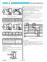
(2) RC connection example 2
Table 3.2 Specification of example 2 (connection method Fig.3.2 (a), (b))
¡
By connecting ALM pin in parallel and series operation, when one
unit has shut down by overvoltage protection or low voltage pro-
tection, other units will be shut down.
¡
When alarm function is not use, please open ALM pin.
¡
Total number of units should be no more than 20 pieces.
3.5 Start in / out (PO pin)
¡
By connecting PO pin, difference of start-up voltage and stop volt-
age can be prevented.
¡
In parallel and series operation, please connect each PO pin mu-
tually.
¡
Total number of units should be no more than 20 pieces.
3.6 Sequence
¡
The sequence time chart of Vin, Vout, PO, ALM and RC pins is
shown in Fig.3.4.
3.4 Alarm (ALM pin)
¡
Normal or abnormal operation of the unit can be monitored by us-
ing the ALM pin.
¡
When OVP or LVP are activated, ALM pin becomes same level as
-Vin pin.
¡
The sink current of ALM pin is 10mA max.
3.7 Isolation
¡
For a receiving inspection, such as Hi-Pot test, gradually increase
(decrease) the voltage for a start (shut down).
Avoid using Hi-Pot tester with the timer because it may generate
voltage a few times higher than the applied voltage, at ON / OFF
of a timer.
DC-DC Converters PCB Mount Type
Instruction Manual
Fig.3.2 RC connection example 2
Between RC and –Vin (VRC2)
Output voltage
10V or more (SFS
O
24 / SFCS
O
24)
20V or more (SFS
O
48 / SFCS
O
48)
or Open
OFF
0V
[
VRC2
[
1.2V or Short
ON
Fig.3.3 ALM circuit
Fig.3.4 Sequence time chart
ALM
-Vin
8V(typ)
10mA(max)
Sink current
Recommended value of R1
Model
SFS
O
24
SFCS
O
24
SFS
O
48
SFCS
O
48
R1
22k
W
220k
W
Value of R2
Model
SFS
O
24
SFCS
O
24
SFS
O
48
SFCS
O
48
R2
200k
W
360k
W
+Vin
RC
-Vin
DC
Input
SW
VRC1
+Vin
RC
-Vin
Photo coupler
DC
Input
VRC1
(a)
(b)
SW
+Vin
RC
-Vin
DC
Input
R1
R2
VRC2
+Vin
RC
-Vin
R1
R2
VRC2
Transistor
(a)
(b)
DC
Input
PO
ALM
RC
20-200ms
LVP set
remote ON
ALM set
start-up
detection
start-up
Vin
Vout
OCP set
200ms(typ)
OFF
ON
ALM reset
SFS/SFCS-22
June 26, 2020


