


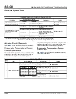
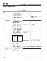


Blower Speed Control Signal From FCU or ACU to Blower
*†
Knob Position
FCU Signal (DC
volts)
‡
Blower Speed (rpm)
Blower Speed Comments
10
5.5+
4000
Constant speed above this range
*
Error conditions can be monitored on the feedback signal line using a digital multimeter equipped with a duty cycle function.
†
Blower speed and diagnostic information are both provided by the BLDC blower motor on the feedback signal wire; however, the FCU and ACU only use the
blower speed information.
‡
These values are based on a system operating voltage of 13.5 VDC.
Table 3, Blower Speed Control Signal from FCU or ACU to Blower
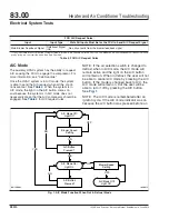
A/C Clutch Circuit
General Operation
The air conditioner compressor clutch is controlled by
the FCU. When certain inputs to the FCU are met,
the FCU sends the A/C request signal to the A/C
clutch relay located in the PDM. This signal is +12
VDC. The request signal causes the A/C clutch relay
to make contact between the common and normally
open contacts of the relay. This allows current to flow
through the relay, then through the binary pressure
switch and to the A/C compressor clutch, thus en-
gaging the compressor.
In steady state operation, compressor cycling is con-
trolled by two things: evaporator temperature sensor
and an internal FCU timer that prevents the com-
pressor from cycling more than four times per min-
ute. The A/C request signal does not become active
until the evaporator temperature sensor is at least
44°F (7°C). See
. Once the signal is active
and as long as the other conditions are met, the sig-
nal remains active until the evaporator temperature
sensor reaches 37°F (3°C), then becomes inactive.
The A/C request signal does not activate again until
the temperature is above 44°F (7°C). With the A/C
on in warm or humid weather, the evaporator tem-
perature will most likely remain between 37 and 44°F
(3 to 7°C), thus keeping the compressor on continu-
ously.
When the blower speed control is set to any speed
other than OFF, and the air selection switch is set to
any setting other than one of the defrost modes, the
user may request A/C by pressing the A/C button.
The light on the button turns on and the FCU is
placed in A/C mode, thus allowing the compressor to
engage when other conditions are met. If the air se-
lection switch is in any of the defrost settings, then
the A/C mode is turned on automatically and cannot
be turned off by pressing the A/C button.
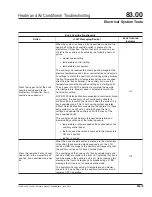
FCU A/C Request Rules
*
Input
Input Type
State All Inputs Must Be for the FCU to Send A/C Request Signal
Ignition power
+12V
On
Evaporator temperature
sensor
Sensor
Above 44°F (7°C)
A/C switch/light
Control panel
On
Air selection switch
Control panel
Any A/C or defrost setting except when rear override is active
Temperature control switch
Control panel
Any
Fan switch
Control panel
Any setting other than off except when rear override is active; fan will
be at least minimum speed.
Compressor cycling timer
Internal FCU logic 15 seconds elapsed since A/C request last active
Heater and Air Conditioner Troubleshooting
83.00
Electrical System Tests
122SD and Coronado Workshop Manual, Supplement 9, June 2014
330/3