background image

Corning Restricted and Confidential Proprietary - Controlled content

SCRN-510 Hardware Installation Guide | DOC-SCRN-510-HIG_i4 | 16 October, 2020 | Page 11

7.1

Flush Mounting the SCRN-510

As shown in 

Figure 3

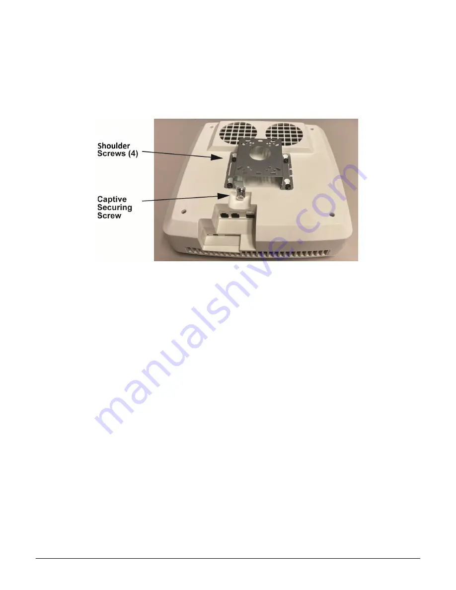
, the SCRN-510 comes with the ceiling-mount bracket attached. This bracket is held to the 

radio node mounting side with four shoulder screws and a captive securing screw, and is non-tilting. The 

shoulder screws should not need to be adjusted but if they do, loosen them slightly to be able to slide the ceil

-

ing-mount bracket on and off of the radio node when the captive securing screw has been loosened. 

Figure 6


shows the captive securing screw and four security screw locations.

NOTE:

The security screws should not need to be adjusted but if they do, loosen them slightly to be able to slide 

the ceiling-mount bracket on and off.

Figure 6

Ceiling-Mount Bracket Screw Locations

Step 1 

Loosen the captive securing screw on the ceiling-mount bracket.

Step 2 

Slide the ceiling-mount bracket toward the captive securing screw to remove it from the SCRN-

510 base.

NOTE:

The shoulder screws should not need to be adjusted but if they do, loosen them slightly to be able to 

slide the ceiling-mount bracket on and off.

Step 3 

Secure the ceiling tethering system. Make sure that it can support the weight of the SCRN-510 

and the ceiling-mount bracket.

NOTE:

Corning recommends that you use a customer-supplied projector mount when hanging the SCRN-510 

from a dropped T-bar ceiling.

Step 4 

Secure the ceiling-mount bracket to ceiling tethering system. 

Step 5 

Slide the radio node back onto the bracket and gently tighten the securing screw.

Figure 7

 shows a typical SCRN-510 mounted to a ceiling tethering system. 

Summary of Contents for SCRN-510

Page 1: ...0 Hardware Installation Guide DOC SCRN 510 HIG_i4 Issue 4 Related Literature Search www Corning com opcomm Click Required Resources Revision History Issue Date Summary of Changes 1 30JUL20 Initial rel...

Page 2: ...mmercial environment This equipment generates uses and can radiate radio frequency energy and if not installed and used in accordance with the instruc tion manual may cause harmful interference to rad...

Page 3: ...n damage the SCRN 510 and internal components Ensure that the SCRN 510 and associated antenna equipment is installed and serviced according to national and local ESD stan dards CAUTION Ensure that the...

Page 4: ...Phoenix Power Cable Ports 8 Section 4 2 SFP Transceiver Port 8 Section 4 3 Micro USB Port 8 Section 4 4 Status LED 8 Section 5 System Specifications 9 Section 6 Compliance 10 Section 7 Mounting the Ra...

Page 5: ...nd high data rates for the coverage footprint The SCRN 510 connects to a Corning centralized unit CU It uses certificate based authentication with the Corn ing CU SCRN 510 radio nodes are managed by t...

Page 6: ...dio Node Configuration Radio Node Model Description Antenna Type SCRN 510 28G1 28 GHz band n261 mmWave RN with 8 x 8 dual polarization antenna array Internal Email Web DMZ Enterprise Mobile Operator C...

Page 7: ...tallation Guide DOC SCRN 510 HIG_i4 16 October 2020 Page 7 3 1 Radio Node Cover Side and Mounting Side Views Figure 2 and Figure 3 display cover and mounting side views of the radio node Figure 2 Radi...

Page 8: ...Transceiver Port The enhanced small form factor pluggable SFP is a compact hot pluggable network interface module The approved SFP included on the Bill Of Materials supports 10 GbE Gigabit Ethernet C...

Page 9: ...x 4 5 in Weight 5 31 kg 11 72 lbs Input Power 2 x 48 VDC Phoenix Power Consumption 100 W Ingress Protection Ingress protection rating IP30 Performance Hardware capable of 4CC up to 32 active users Pea...

Page 10: ...gles 0 15 30 and 45 Figure 5 shows the SCRN 510 tilt options Figure 5 Mounting Bracket Downtilt Options NOTE Always consult and follow local codes for mounting and wiring Corning equipment When possib...

Page 11: ...do loosen them slightly to be able to slide the ceiling mount bracket on and off Figure 6 Ceiling Mount Bracket Screw Locations Step 1 Loosen the captive securing screw on the ceiling mount bracket S...

Page 12: ...tached and has the multi angle wall mount bracket loose in the box Figure 8 shows the SCRN 510 wall mount bracket Figure 8 SCRN 510 Wall Mount Bracket When using the multi angle wall mount bracket it...

Page 13: ...mount bracket to the wall Figure 10 shows the SCRN 510 wall mount bracket attached to a wall Figure 10 Wall Mount Bracket Attached to a Wall NOTE Production wall mount brackets will have a large hole...

Page 14: ...o time during installation impede inserting the radio node into the mounting brackets 9 Completing the Installation Step 1 Make sure that the captive securing screws are tightened The radio node is no...

Page 15: ...adio node moves to the next state State 3 upon receiving a DHCP response and an IP Address No DHCP Response IP Address not allocated Check cabling DHCP Server configuration 3 Join Solid Blue The radio...

Page 16: ...mmand to verify the configuration show System RadioNode LED DefaultMode Dark 12 2 Re Enabling the LED Display Step 1 From the Configuration Mode issue the set System RadioNode LED DefaultMode Standard...

Page 17: ...est a login if you meet these criteria Corning Optical Communications LLC 4200 Corning Place Charlotte NC 28216 USA 800 743 2675 FAX 828 325 5060 International 1 828 901 5000 www corning com opcomm Co...

Reviews: