background image

Cornell Communications, Inc 


4800 Installation Manual 07-31-18 


24 


4800 System Troubleshooting 

The 4800 System is shipped from the factory fully programmed and tested with the local site information that 
was provided by a Cornell Communications dealer.  If you have any difficulties with the installation, consult the 
troubleshooting chart below. 

Control Panel Symptoms 


Resolutions 


Power LED off   


Confirm 24VDC system power at J10 terminal. 


Control Panel “Fault” is displayed 


Confirm phone line is connected.  


Display is “Dim”  


The display reduces brightness automatically. 


No “Dial Out” of  phone message 


No phone line or connection. 

System must be programmed to call “Off Site” 

Call Stations 


Resolutions 


No 10 second LED flash   


Confirm station wiring. 

Stations do not operate below 18VDC 


Station activation shows 


Station is not programmed into system. 

       00:21:c3:00:00:XX 

 
The 4800 system device connections are fully supervised.  Any Control Panel, Expansion Switch, or Call Station 
that is programmed into the system, will display a “Fault”, at the Control Panel(s), if they lose power, are 
damaged, or disconnected from the circuit. 

*All “Fault” indications must be manually cleared from the system, upon repair of the defective device.  To clear 
all faults, press the “Clear All Calls” button twice, at the Main Control Panel.  The “Clear All Calls” function only 
functions from the Control Panel designated as the “Main Control Panel” in the system. 


Power Supplies 

The B-5248A and B-5243B have the same safety features as outlined below. Confirm proper 24VDC is available 
to the 4800 system. Both supplies provide an average of 26 to 27VDC, in order to charge the battery circuit, and 
are normal operating voltages. Each supply includes (2) 12V 7ah batteries. 


PTC Class 2 protected outputs. 


Short circuit/Overload protection. 


AC/DC power LED indicators. 


AC/DC fail relays. 

Refer to the individual manuals included with the power supplies.  


Summary of Contents for 4800 series

Page 1: ...Emergency Communication System Series 4800 Installation Manual Cornell Communications Inc Milwaukee WI 53223 USA 800 558 8957 ...

Page 2: ...nclosure Installation 11 4800 System Riser 12 System Wiring Terminations 13 14 Technical Specifications Electrical Ratings 15 16 Power Supply Specifications 16 EMI Filter Installation Power Supply Connections 17 Power Supply Fault Detect 18 TIA EIA 568 A and 568 B Pin Out 19 Dedicated Phone Line Connection 20 VoIP Phone Line Option 21 Cell Phone Line Option 22 4800V Call Station Auxiliary Contact ...

Page 3: ...nications manufactures proprietary Control Panels and Switches that have 8 available RJ45 ports to connect to additional Remote Control Panels Switches and Call Stations These devices connect using the straight thru TIA EIA 568A or TIA EIA 568B wiring standard Any attempt to connect an Off the Shelf Ethernet switch will damage the system and void all warranty 2 Warning The 4800 Digital Emergency C...

Page 4: ...d indoor dry environment with temperatures maintained between 55 F and 95 F Features can include up to 4 Remote Control Panels and connecting a total of 255 Call Stations The 4800 Digital Emergency Communication System shall poll supervise all the Call Stations Control Panels and Expansion Switches on a continuous basis to identify line faults and defective equipment Faults will be alerted and dis...

Page 5: ...Cornell Communications Inc 4800 Installation Manual 07 31 18 5 4800 System Components ...

Page 6: ...e 4800V Call Station will connect 2 way voice communication between the Control Panel s handset and the 4800V Call Station The Control Panel s operator will immediately be connected to listen talk to the person at the 4800V Call Station Momentarily depressing the Select Top Row button again will disconnect voice communication to the 4800V Call Station and complete the call Any Control Panel may re...

Page 7: ...row of the display and pressing the Select Top Row button or by pressing the Mute Alarm button Either action will immediately terminate the phone conversation and connect a voice path from the Control Panel s to the 4800V Call Station System Faults The modem phone line circuit integrity is checked every 24 hours In the event of a failure a Fault notification will appear on the Control Panel s disp...

Page 8: ...ions Cat5e connections are limited to 328 between the Control Panel Switches and Call Stations Hardware Installation Power Supply s The Cornell listed power supply s can be located in a controlled maintenance room or closet up to 478 away from the Control Panel s or Expansion Switch s The enclosures have keyhole slots for surface mounting Power supplies require 120VAC 60Hz 2 5 A Max hardwired conn...

Page 9: ... INCHES INCHES INCHES LBS 7330 122 Enclosure Chassis 3 25 18 25 18 25 Rough Opening Dimension 3 50 18 75 18 75 7330 123 Enclosure Frame Door 1 50 20 00 20 00 Assembled Enclosure 22 Installation 1 Cut an 18 square rough opening in the approved location 2 Use the hardware supplied and the 4 round holes to mount the back box 1 8 to 1 4 below the finished surface as shown Note the Top of Box arrow for...

Page 10: ...ly Installation Cont 1 Mount the Control Panel s using 4 of the 10 32 Lock Nut hardware that is provided Ensure the field wiring moves freely and is not pinched behind the Control Panel s prior to tightening 2 Mount the Handset Cradle on the desired side using 2 of the 10 32 Lock Nut hardware that is provided 3 Connect the field wiring according to the wiring instructions starting on page 13 4 Ens...

Page 11: ...ame assembly into the back box accordingly 2 Insert 2 of the 4 X 5 8 SS screws into the hinge side of the Door Frame assembly Do not over tighten 3 Insert the remaining 4 screws and adjust the frame to align with the door when the door is closed Caution Over tightening the screws will warp or bend the Door Frame assembly and may cause the hinge to operate improperly Installation Cont 1 Surface mou...

Page 12: ...Cornell Communications Inc 4800 Installation Manual 07 31 18 12 4800 System Riser ...

Page 13: ...Remote Switches or Call Stations Standard straight thru TIA EIA 568A or TIA EIA 568B See page 18 Caution Do not connect a PC to these ports The ports have DC voltage to power the Call Stations Connecting to any of these ports will damage the PC J4 WAN port used to connect additional Remote Control Panels and Expansion Switches Standard straight thru TIA EIA 568A or TIA EIA 568B J6 USB programming ...

Page 14: ...tional Control Panel s can be connected to expand the system by following the same procedure o Connect a Cat5e cable from the A H J2 port of the existing Control Panel s to the WAN J4 port of the Add On Control Panel or Expansion Switch This will provide an additional 8 Call Station connections Subtract 1 J2 port if expanding further Note Additional Control Panel s and Expansion Switches can be ad...

Page 15: ...ainted The enclosure assembly consists of a separate back box and a locking hinged Frame Door assembly The Back Box chassis should be mounted with the Top of Box Arrow pointing up and approximately 1 4 below the finished wall surface The reversible Frame Door assembly can be adjusted up to approximately 1 away from the face of the chassis surface Control Panel Enclosure DEPTH WIDTH HEIGHT INCHES I...

Page 16: ...ion Screw terminals Exterior Tan baked enamel finish Dimensions 11 25 H x 15 75 W x 4 50 D Weight w Bat 21 Lbs Mounting Slotted keyholes make it suitable for vertical wall mounting Unit comes complete with power supply enclosure cam locks battery leads 2 12V 7ah batteries and installation instructions Model B 5243B Battery Back UP Power Supply The Cornell B 5243B is UL 1481 listed Input Specificat...

Page 17: ...Cornell Communications Inc 4800 Installation Manual 07 31 18 17 EMI Filter Installation Power Supply Connections ...

Page 18: ...Cornell Communications Inc 4800 Installation Manual 07 31 18 18 Power Supply Fault Detect ...

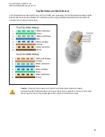
Page 19: ...d in 2002 Both standards define the T 568A and T 568B pin outs for using Unshielded Twisted Pair cable and RJ 45 connectors for Ethernet connectivity Caution Properly trained personnel familiar with Telecommunications Industry Associations 568 TIA EIA standard are required for proper installation Failure to terminate the wiring correctly will cause damage to the system and void the warranty ...

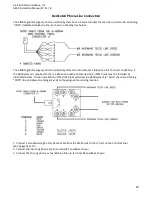
Page 20: ...e Seizure capability If the 4800 system is required to share a phone line with another device an RJ31X jack must be installed as illustrated below Proper installation of the RJ31X jack will allow the 4800 system to Seize the shared analog POTS line and place an emergency call to the assigned monitoring location 1 Connect a standard straight thru Cat5e cable from the RJ31X jack to the J7 port on th...

Page 21: ...ethod of offsite voice connection if the phone service internal external network or power system fails the 4800 system will not be able to connect to the offsite monitoring location The example VoIP service disclaimers below are generally included with service contracts Several manufacturers offer analog voice phone adapters Please confirm with the current prospect VoIP service for the correct cer...

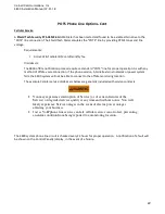
Page 22: ...work or power system fails the 4800 system will not be able to connect to the offsite monitoring location The example Cellular service disclaimers below are generally included with service contracts The 4800 system phone line circuit is checked every 24 hours for proper operation A notification of a fault will be shown on the Control Panel s display in the event of a failure You may experience int...

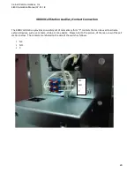
Page 23: ... The 4800V call station provides an auxiliary set of momentary form C contacts that can be used to activate external devices such as a camera strobe or tone device Please refer to the picture of the rear view of the call station below The contacts are labeled on the side of the switch as follows NC NO C NC NO C ...

Page 24: ... 00 00 XX The 4800 system device connections are fully supervised Any Control Panel Expansion Switch or Call Station that is programmed into the system will display a Fault at the Control Panel s if they lose power are damaged or disconnected from the circuit All Fault indications must be manually cleared from the system upon repair of the defective device To clear all faults press the Clear All C...

Page 25: ...peration the 4800 system should be tested on a regular basis by qualified personnel Power Supply Maintenance Each Unit should be tested at least once a year for the proper operation as follows Output Voltage Test Under normal load conditions the DC output voltage should be checked for proper voltage level 24VDC Battery Test Under normal load conditions check that the battery is fully charged check...

Page 26: ...verify OEM warranty with your Cornell Regional Account Manager if you have any questions Returns Warranty returns will be accepted with RMA for no cost Defective materials will be repaired for a minimum of 100 and cost of the repair will be for time and materials not to exceed the cost of a new unit Returns of unused unmarked boxed equipment are subject to a MANDATORY 25 restocking charge when ret...

Reviews: