Cooper RADIO-900M Installation Instructions Manual Download Page 5


Installation Instructions: RADIO-900M 
P/N P01-04941 Rev-A 

I

N

S

T

A

L

L

A

T

I

O

N


I

N

S

T

R

U

C

T

I

O

N

S


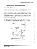
5.2.3  ANT-810-YAGI Yagi Directional Antenna 

Table 5 ANT-810-YAGI Specifications 

ANT-810-YAGI SPECIFICATIONS 

Frequency


900 - 930 MHz


Gain


10 dBi


Bandwidth


30 MHz


VSWR


< 1.5:1 across band


Polarization


Vertical (when mounted vertically)


H Plane


50

°


E Plane


46

°


F/B Ratio


17 dB


Length


35.4" (90 mm)


Construction


Aluminum


Mounting


Use with BR-COL-KIT for mounting on poles up to 1.9" (50 mm)


Termination


N-Type female on 5.9" cable (50 mm), 50 ohm


Wind Loading


10 lbs (4.6 kg) at 99 miles/hour (160 km/hour)


Installation must always be conducted by a qualified, factory trained 
technician. 

5.2.4  Antenna Wiring Kits 

Table 6 Antenna Wiring Kits 

Description 

Part Number 

Standard LMR-400 Kit 

CAB-LMR-400-KIT 

Standard LMR-600 Kit 

CAB-LMR-600-KIT 

Premium Rated LMR-400 Kit 

CAB-LMR-400PR-KIT 

Premium Rated LMR-600 Kit 

CAB-LMR-600PR-KIT 


Summary of Contents for RADIO-900M

Page 1: ...ng near electricity do not use metal rules flashlights metallic pencils or any other object having exposed conducting material Ensure all electrical connections are secure before applying power to a u...

Page 2: ...ased on site specific requirements ANT 805 OM ANT 808 OM ANT 810 YAGI 3 One of the following must be installed and operable prior to installing the RADIO 900M IPC 8000 HPSA 8100 R ACU 8411 4 Screwdriv...

Page 3: ...232 Serial Port RTS CTS DTR signaling GENERAL SPECIFICATIONS Ethernet Port 10 100 Base T RJ45 Terminal Block Wire Size 12 AWG max LED Indicators Module Status Serial RX and TX Radio Link Ethernet Act...

Page 4: ...z VSWR 1 5 1 across band Polarization Vertical H Plane Omni directional Length 35 4 90 mm Construction Fiberglass enclosed colinear Mounting Aluminum ferrule with BR COL KIT Termination N Type female...

Page 5: ...46 F B Ratio 17 dB Length 35 4 90 mm Construction Aluminum Mounting Use with BR COL KIT for mounting on poles up to 1 9 50 mm Termination N Type female on 5 9 cable 50 mm 50 ohm Wind Loading 10 lbs 4...

Page 6: ...ht paths are only necessary to obtain the maximum range obstructions in the radio path will reduce the range however may not prevent a reliable path Care must be taken with placement of antenna in rel...

Page 7: ...the TX RX connector An RF Path Link Budget must be calculated by a qualified technician prior to defining the following Location of the RADIO 900M Antenna type and location Length of cable run s and...

Page 8: ...Top of RADIO 900M 6 Using the 2 conductor cable provided in the RADIO 900M connect the DC power from the and supply connectors on the terminal block located on bottom of the RADIO 900M to pins 1 and...

Page 9: ...on the top of the IPC to the RJ 45 connector located on the bottom of the RADIO 900M 8 The RADIO 900M installation is complete close and secure the enclosure 9 Refer to the IPC 8000 Installation Instr...

Page 10: ...enclosure mount the DIN Rail Bracketto the mounting holes on the back panel of the HPSA 8100 R to the left of the control panel as shown in Figure 9 2 Mount the RF connector bracket to the mounting ho...

Page 11: ...closure and as close to the RF entry point as possible 2 Connect the RF cable from the Antenna to the N type Female connector on the SPD 3 Connect the RF Cable exiting the HPSA or IPC 8000 cabinet to...

Page 12: ...ide reasonable protection against harmful interference when the equipment is operated in a commercial environment This equipment generates uses and can radiate radio frequency energy and if not instal...

Reviews: