


P84453 L
Sheet 3 of 4
WARNING: THE SPEAKER STROBE APPLIANCE MUST BE FIELD SET TO THE DESIRED dBA SOUND OUTPUT LEVEL BEFORE IT IS
INSTALLED. THIS IS DONE BY PROPERLY INSERTING JUMPER PLUGS IN ACCORDANCE WITH THESE INSTRUCTIONS. INCORRECT
SETTINGS WILL RESULT IN IMPROPER PERFORMANCE, WHICH COULD RESULT IN PROPERTY DAMAGE AND SERIOUS INJURY OR
DEATH TO YOU AND/OR OTHERS.
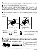
Table 4: Speaker Voltage and Wattage Connection Chart
Position 25V 70V
A 8
------
B 4
------
C 2
------
D 1 8
E 1/2 4
F 1/4 2
G 1/8 1
H ------
1/2
I ------
1/4
J ------
1/8
Figure 5:
135
185
CANDELA
POINTER
NOTE:
The ET70 and ET90-24MCWH comes pre-set at 185cd.
WARNING: THE CANDELA SELECT SWITCH MUST BE FIELD SET TO THE REQUIRED CANDELA INTENSITY BEFORE INSTALLATION.
WHEN CHANGING THE SETTING OF THE CANDELA SELECT SWITCH, MAKE CERTAIN THAT IT “CLICKS” IN PLACE. AFTER CHANGING
THE CANDELA SETTING, THE APPLIANCE MUST BE RETESTED TO VERIFY PROPER OPERATION. IMPROPER SETTING OF THE CANDELA
SELECT SWITCH MAY RESULT IN OPERATION AT THE WRONG CANDELA, WHICH COULD RESULT IN PROPERTY DAMAGE AND SERIOUS
INJURY OR DEATH TO YOU AND/OR OTHERS.
MOUNTING PROCEDURES:
1.
These models can be flush mounted to a 4” square by 2-1/8” deep backbox with a 4” square 1-1/2” extension ring (Figure A) or surface mounted to a surface
backbox (Figure B). Mounting hardware for each mounting option is supplied.
2.
Conduit entrances to the backbox should be selected to provide sufficient wiring clearance for the installed product. Do not pass additional wires (used for other
than the signaling appliance) through the backbox. Such additional wires could result in insufficient wiring space for the signaling appliance.
3.
When terminating field wires, do not use more lead length than required. Excess lead length could result in insufficient wiring space for the signaling appliance.
4.
Use care and proper techniques to position the field wires in the backbox so that they use minimum space and produce minimum stress on the product. This is
especially important for stiff, heavy gauge wires and wires with thick insulation or sheathing.
5.
These models have an integrated speaker mounting plate which must be oriented correctly when it is mounted to the backbox. Turn the speaker mounting plate so
that the arrow above the words “Horizontal Strobe” points to the top side of the speaker mounting plate.
6.
To move selector switch, insert screwdriver into slot shown on the bottom side of the strobe. The setting is indicated by a pointer and can be seen on the bottom
side of the lens. See Figure 5.
7.
Mount the speaker mounting plate to the backbox. Next slide the grille over the speaker mounting plate strobe and attach with (2) screws.
WARNING: THE SPEAKER STROBE APPLIANCE IS A "FIRE ALARM DEVICE - DO NOT PAINT."
WARNING: WHEN INSTALLING STROBES IN AN OPEN OFFICE OR OTHER AREAS CONTAINING PARTITIONS OR OTHER VIEWING
OBSTRUCTIONS, SPECIAL ATTENTION SHOULD BE GIVEN TO THE LOCATION OF THE STROBES SO THAT THEIR OPERATING EFFECT
CAN BE SEEN BY ALL INTENDED VIEWERS, WITH THE INTENSITY, NUMBER, AND TYPE OF STROBES BEING SUFFICIENT TO MAKE SURE
THAT THE INTENDED VIEWER IS ALERTED BY PROPER ILLUMINATION, REGARDLESS OF THE VIEWER'S ORIENTATION. FAILURE TO
DO SO COULD RESULT IN PROPERTY DAMAGE AND SERIOUS INJURY OR DEATH TO YOU AND/OR OTHERS
The 135/185cd settings are Listed for use in sleeping or non-sleeping areas when installed in accordance with appropriate NFPA Standards and the Authority Having
Jurisdiction.
WARNING: INSTALLATION OF COOPER NOTIFICATION 138/185 CANDELA STROBE PRODUCTS IN SLEEPING AREAS SHOULD BE
WALL MOUNTED AT LEAST 24" BELOW THE CEILING AS FOLLOWS: (1) THE ON-AXIS (DIRECTLY IN FRONT OF LENS) LIGHT OUTPUT
SHOULD BE DIRECTED AT THE EYE-LIDS OF THE SLEEPING PERSON, E.G. PILLOW END OF BED, BED HEAD; (2) NO PART OF THE BED
SHALL BE MORE THAN SIXTEEN (16) FEET FROM THE STROBE NOTIFICATION APPLIANCE. INSTALLERS MUST ADVISE OWNERS AND
OPERATORS OF BUILDINGS WITH SLEEPING OCCUPANTS, E.G. HOTELS AND MOTELS, TO WARN GUESTS, RESIDENTS AND EMPLOYEES
TO NOT MOVE THE BED LOCATION TO A POSITION VIOLATING POINTS (1) AND (2) ABOVE OR SERIOUS INJURY AND/OR LOSS OF LIFE
MAY OCCUR DURING A FIRE EMERGENCY.
NOTE:
NFPA 72/ANSI 117.1 conform to ADAAG Equivalent Facilitation Guidelines in using fewer, higher intensity strobes within the same protected area.


