

HALO
®
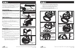
SWITCH
LAMP
(do not twist)
Do not touch
lamp with bare
fingers - hold
lamp with cloth
FIG. 7
FIG. 10
HALO
®
TRACK
POLARITY
GROOVE
INSERT FIXTURE
IN TRACK AND
THEN TWIST 90°
FIXTURE
POLARITY
GROOVE
FIXTURE
POLARITY
GROOVE
THUMB
LATCH
FIG. 1C
FIG. 1D
To install the fixture to the track, insert the contact assembly into the track and
rotate the fixture neck 90° so the polarity line on the power supply aligns with
the polarity line on the track. Pull back and release the thumb latch allowing
the power supply to lock into position (Fig 1C and 1D).
To remove the fixture, slide thumb latch down until latch is clear of the track
channel opening. Twist the fixture neck and turn (90°) until the contact
assembly is free and remove power supply from track.
Installation Instructions for
LA5300 Series Track Fixture (Fig. 2)
The LA5300 track fixture can be used with Halo two circuit Architectural Track.
Fixture can be rotated 180° to second circuit.
To install fixture into track, open switch cover so that contacts are concealed
inside fixture. Insert fixture into track so the contact will engage the desired
circuit. Close switch cover.
To remove fixture, rotate switch cover 90° and remove from track. (Fig. 2)
Installation Instructions for
LF5300 Series Track Fixture (Fig. 3)
The LF5300 track fixture can be used with Halo ‘LF’ series 2 two-circuit track
only.
Step 1.
Open connector cover by pulling downward on the connector sleeve
and connector cover so that the contacts are exposed.
Step 2.
Raise fixture to track with contacts facing intended circuit.
Step 3.
Move connector into position and close connector cover until it snaps
into position.
To remove fixture from track.
Step 1.
Open connector cover by pulling downward on the connector sleeve.
Step 2.
Raise fixture from track and remove.
Note:
To access the other circuit, rotate fixture 180 degrees and follow
installation instruction above.
Relamping Instructions
Warning:
Before working on fixture, be sure to turn off AC power or remove
fixture from track.
Step 1
Allow unit to cool then remove from track
Step 2
Remove bezel and glass assembly by rotating assembly counter-
clockwise (Figs 4 & 5).
Step 3
Remove glare shield by pulling both ends of the glare shield straight
out (Fig. 6).
Step 4
Locate the relamp label on the outer surface of the reflector to deter-
mine the required lamp wattage for proper fixture operation (Fig. 6).
Step 5
Remove the existing lamp by pulling straight out.
Step 6
Using a soft cloth to avoid contacting the new lamp with bare hands,
insert the replacement lamp into the socket by carefully aligning the
lamp pins to the socket and pushing the lamp straight into the
socket without twisting (Fig. 7). Insure lamp pins are inserted
properly into the socket for proper lamp function.
FIG. 2
FIG. 3
BEZEL & GLASS
ASSEMBLY
FIG. 4
CONNECTOR COVER
CONNECTOR
SLEEVE
Customer First Center • 1121 Highway 74 South • Peachtree City, GA 30269 • 770.486.4800 • FAX 770.486.4801
11/06 rev.4 702505
Customer First Center • 1121 Highway 74 South • Peachtree City, GA 30269 • 770.486.4800 • FAX 770.486.4801
11/06 rev.4 702505
FIG. 9
REFLECTOR
HOUSING
FIG.8
LUGS
Step 7
Replace the glare shield and bezel and glass assembly by carefully
engaging all three lugs on the bezel with the corresponding lugs on the
reflector housing (Fig. 8). Turn the bezel and glass assembly clockwise
until the positive ‘click’ is felt, indicating the home position has been
engaged in the reflector housing (Fig. 9). Verify the bezel and glass
assembly is securely retained in the reflector housing.
Step 8
DO NOT OPERATE FIXTURE WITHOUT GLASS LENS. RISK OF FIRE.
Be sure on-off switch is returned to ON position (Fig 10).
FIG. 5
FIG. 6
GLARE SHIELD
BEZEL &
GLASS
ASSEMBLY
RELAMP
LABEL


