


5
ACSC IO&M
B51002-002
5. Align setscrews bearing to bearing and secure tightly
to the shaft.
NOTICE! Never tighten both pairs of setscrews be-
fore securing bearing mounting bolts. This may
damage the shaft.
6. Inspect the wheel position again. If necessary, read-
just by loosening the bearing bolts and setscrews and
repeat from step 5.
Wheel Replacement
1. Drill two holes approximately centered between the
shaft and the edge of the hub OD with the following
dimensions:
• 1/4” diameter
• 3/8” to 1/2” deep
• 180° apart in face of hub
2. Tap 1/4” holes to 5/16” thread with the 5/16” hole tap.
Do not drill or tap any larger than recommended.
• 1/4” diameter
• 3/8” to 1/2” deep
• 180° apart in face of hub
3. Tap 1/4” holes to 5/16” thread with the 5/16” hole tap.
Do not drill or tap any larger than recommended.
4. Screw the puller arms into the tapped holes full depth
of threads (3/8” to 1/2” approximately). Align center of
puller with center of shaft. Make certain all setscrews
in hub (normally a quantity of two) are fully removed.
Work puller slowly to back wheel off the shaft.
Recommended Puller
Lisle No. 45000 Steering Wheel Puller. This puller is
available at most automotive parts retail outlets.
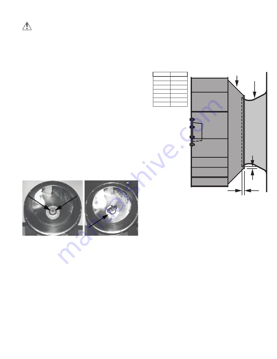
Wheel Puller
Drilled Hole Location
Wheel-to-Inlet Clearance
The correct wheel-to-inlet clearance is critical to proper
fan performance. This clearance should be verified before
initial start-up since rough handling during shipment could
cause a shift in fan components. Refer to wheel/inlet draw-
ing for correct overlap.
Adjust the overlap by loosening the wheel hub and mov-
ing the wheel along the shaft to obtain the correct value.
A uniform radial gap (space between the edge of the
cone and the edge of the inlet) is obtained by loosening the
inlet cone bolts and repositioning the inlet cone.
OVERLAP
RADIAL
CLEARANCE
WHEEL SHROUD
INLET
Size
Overlap
100–165
3/16”
180–245
1/4”
270–300
5/16”
330–365
3/8”
402
7/16”
445–490
1/2”
540–730 13/16”