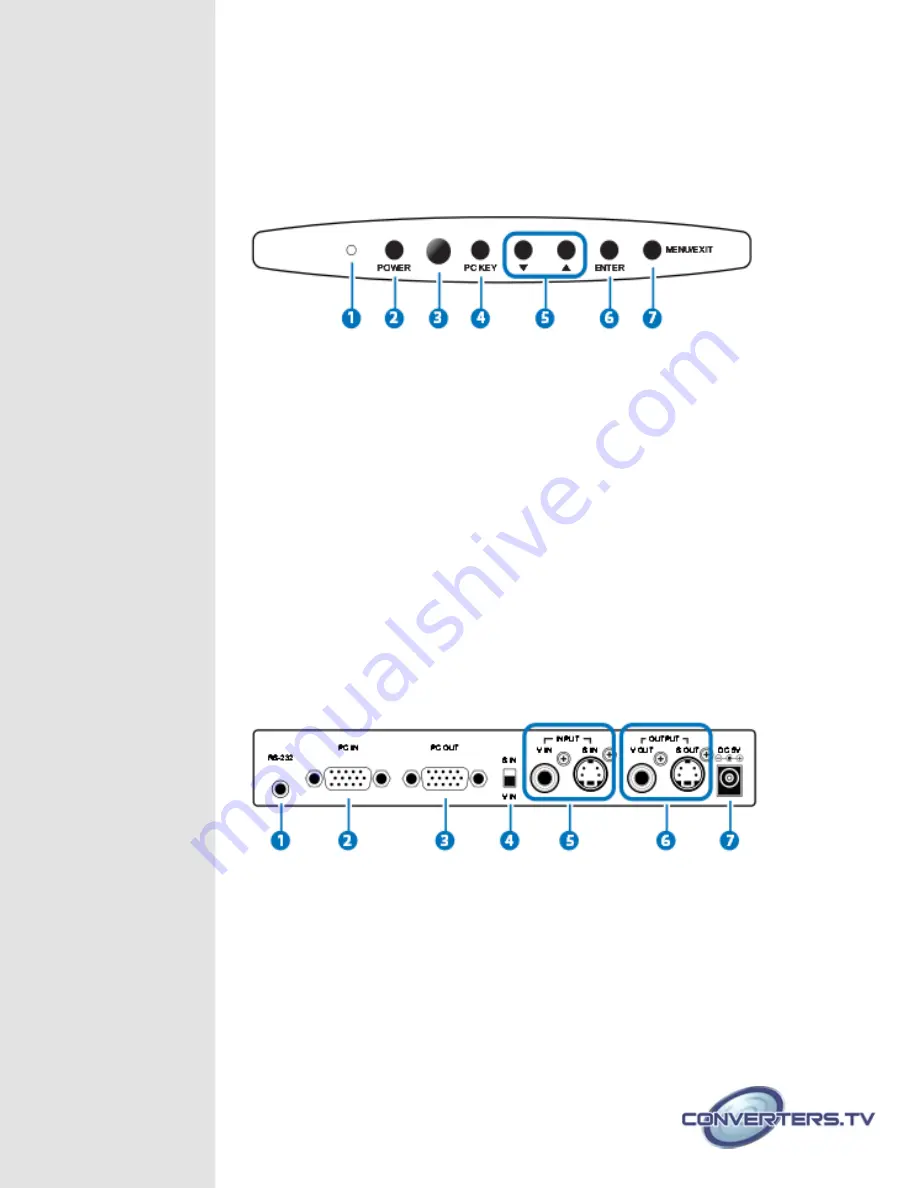
Operation Controls
and Functions
The following sections describe the hardware components of the unit.
Front Panel
1.
POWER LED INDICATOR
The LED will illuminate when power is on.
2.
POWER
Press to power on the system, press again to turn the system to
standby.
3.
IR SENSOR
4.
PC KEY
Press the button to display PC screen or the combination of PC
and Video or S-Videio screen.
5.
▲
and▼
Press to toggle through various control or setting values.
6.
ENTER
Press to enter or to confirm the selection.
7.
MENU/EXIT
Press to enter MENU mode and press again to EXIT the menu or
return to previous page.
Back Panel
1.
RS-232
Connect 3.5mm phone jack to D-Sub 9pin adaptor to the PC/
Notebook device for RS-232 control.
2.
PC INPUT
Connect the input source equipment such as PC/NB for PC signal
input.
3.
PC OUTPUT (PASS THROUGH)
Connect the display TV/monitor for PC signal output.
4.
V-IN AND S-IN
Switch between Video or S-Video input.
5.
VIDEO/S-VIDEO INPUT
Connect the Video/S-Video input port to the source equipment


