1
E
E
E
E
E
E
E
E
E
E
F
F
F
F
2
2
7
6
5
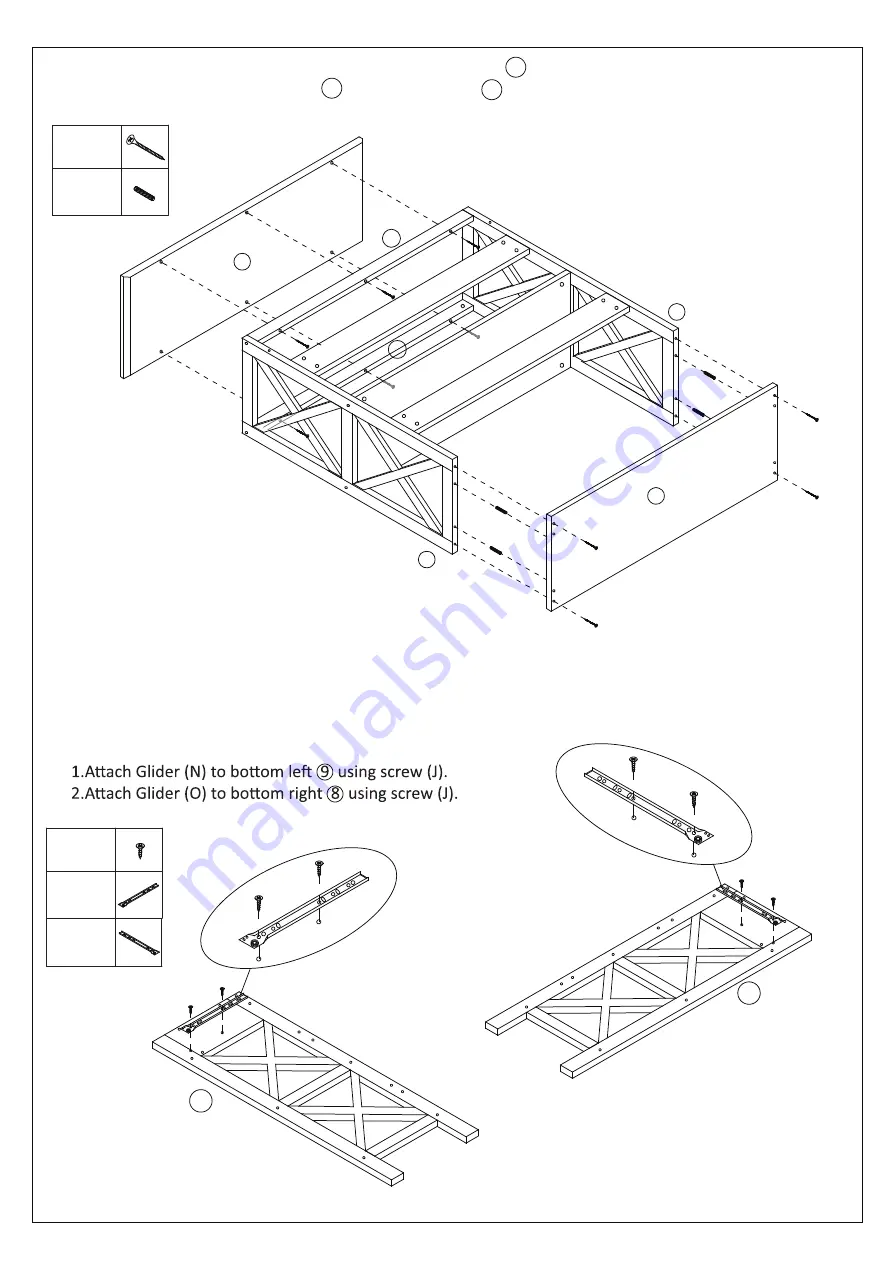
Step 4
8
J
J
J
9
J
N
O
Step 3
1.Insert Wooden Dowels (F) into Middle Panel .
2.Connect Top Panel and Middle Panel to assembly using Screws (E),as shown.
5
5
1
Page 5 of 8
4 X (J)
1 X (N)
1 X (O)
10 X (E)
4 X (F)
N
J
J
O
J
J


