background image

31

CONVAID USER’S GUIDE

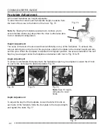
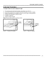
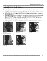
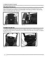
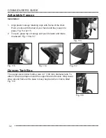
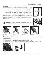
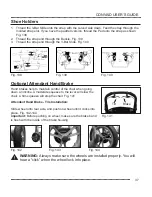
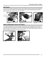
Fig. 108

Fig. 109

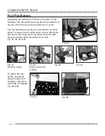
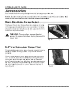
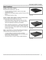
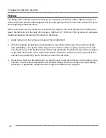
Occi Headwing

The Occi Headwing comfortably positions the head in alignment. To attach, thread the straps 
through the slits in the back upholstery and attach at the back of the chair. For added secure-
ment, thread laces through the grommet holes in the upholstery, and tie. Fig. 108–113. If the Occi 
Headwing is mounted to the headrest extension, wrap the straps around the headrest extension 
and secure by lacing the threads through the grommet holes.


Fig. 110

Fig. 112

Fig. 111

Fig. 113

Summary of Contents for Rodeo RD10

Page 1: ...ENGLISH User s Guide Rodeo Lightweight Tilt In Space Wheelchair SAVE THIS BOOK FOR FUTURE REFERENCE READ INSTRUCTION BEFORE USING...

Page 2: ...duced transmitted transcribed stored in a retrieval system or translated to another language or computer language in any form or by any means electronic mechanical magnetic optical chemical manual or...

Page 3: ...h 15 Seat Depth 16 Seat Depth Adjustment Without Seating 16 Seat Depth Adjustment With Seating 17 Tilt Adjustment 17 Recline Function 18 Fabric Removal 19 Seat Upholstery Attachment 20 Pelvic Position...

Page 4: ...upport Surface Tray 38 Calf Panel 39 Height Adjustable Flip Up Armrests 39 Solid Mesh Side Panels 40 Seat Cushions 41 Fitting 42 Caution 43 Transit Models Transit Option 44 Transit Mode Instructions 4...

Page 5: ...ation is necessary please contact your Convaid provider If you do not follow all instructions and warnings damage to the chair or serious injury may occur The latest version of all instructions and pr...

Page 6: ...transit CHOOSE THE RIGHT CHAIR SAFETY OPTIONS There are several options available to meet the needs of the wheelchair user Make sure that your and your health care provider s choice of chair and other...

Page 7: ...AKE SURE that the chair operates properly Repair any problems before use ALWAYS verify that the quick release axles are locked so that the back wheels do not come off ALWAYS secure the user into the c...

Page 8: ...efore removing the user from the chair and before returning the user to it always engage the wheel lock Never remove or place user without engaging the wheel lock WARNING Never leave the user unattend...

Page 9: ...Never use this chair on an escalator because the chair may tip over WARNING Many of the screws bolts and nuts used on this chair are specialized or high strength fasteners Only use fasteners purchase...

Page 10: ...table Push Handle Tilt Adjustment Lever Single Foot Activated Wheel Lock Bar 11 5 x 2 5 Rear Solid Wheels Medical Necessity Storage Basket Option One Piece Angle Adjustable Footplate 7 5 x 2 Front Sol...

Page 11: ...o Without Seating Overview Chair Warning Label 11 5 x 2 5 Rear Solid Wheels Release Strap Recline Tilt Adjustment Lever 7 5 x 2 Front Solid Wheels One Piece Angle Adjustable Footplate Depth Adjustable...

Page 12: ...15 21 16 22 18 24 Footplate Adjustment Angle 20 20 20 20 Seat to Footplate 9 14 9 14 11 16 13 18 Seat to Footplate 7 13 7 13 9 5 15 5 12 18 Weight Capacity Regular Transit 75 66 lbs 75 66 lbs 100 100...

Page 13: ...19 15 21 16 22 18 24 Footplate Adjustment Angle 20 20 20 20 Seat to Footplate 9 14 9 14 11 16 13 18 Seat to Footplate 7 13 7 13 9 5 15 5 12 18 Weight Capacity Regular Transit 75 66 lbs 75 66 lbs 100...

Page 14: ...ing 3 Remove the chair from the packaging material 4 Check to make sure that your order is complete Preparing the Chair for Use Once you have all components as ordered the directions for use in this U...

Page 15: ...ng Wheel Lock Operation 1 Lock the wheels by pushing the wheel lock bar downward Fig 5 2 Disengage the wheel lock by pulling the wheel lock bar upwards with the top of your foot Fig 6 DOWN UP 1 Press...

Page 16: ...y visual inspection on both sides Fig 14 15 Fig 12 Fig 14 Fig 15 Fig 13 WARNING Make sure the safety lock clicks into place Two clicks will be heard Fig 14 Unfolding the Chair Fig 7 1 Lay chair down w...

Page 17: ...are visible and fully exposed on both sides Fig 15 Folding the Chair Fig 19 Fig 20 Fig 21 Fig 22 1 Before folding front wheels of chair should be in a forward facing position Fig 19 2 Apply wheel lock...

Page 18: ...squeeze them together with one hand With the other hand hold top of push handle pulling towards you Fig 28 29 6 Push chair downward into the folded position Fig 30 7 Push in gray buttons on the push h...

Page 19: ...pport the head To determine the back height measure from the seat to the upper part of the head Fig 35 Seat Back Height Seat back height Correct seating and positioning encourages good posture which i...

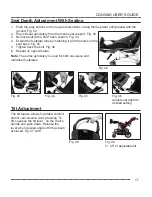
Page 20: ...nut on the bottom of the seat pan Do not remove nut from bolt Fig 39 2 Using the same tools from step 1 remove the horizontal facing nut located under the seat pan from both the right and left side Fi...

Page 21: ...45 5 Tighten back the bolt Fig 46 6 Repeat on opposite side Fig 44 Fig 46 Adjust seat depth to desired setting Fig 45 Fig 43 Fig 42 Seat Depth Adjustment With Seating Note The same upholstery is used...

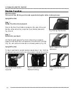
Page 22: ...eat back Lift Push Handle upward Fig 52 to relieve the occupant s weight At the same time pull upwards on the Recline Pull Ring Fig 53 and recline the seat back to desired position Fig 54 Upright Posi...

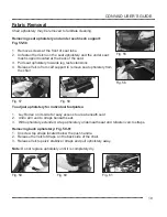
Page 23: ...to remove seat upholstery from the chair Removing back upholstery Fig 59 61 1 Unscrew top straps located below the push handle 2 Release the Velcro Straps on the back side of the chair 3 Release Velc...

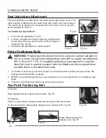
Page 24: ...s as a user restraint or on an occupant who is comatose or agi tated 3 Failure to heed these warnings may cause serious injury Two Point Positioning Belt Fig 65 Fig 66 Fig 67 To Buckle Snap together t...

Page 25: ...with Padded Covers Optional Feature The strap is connected with the gray quick release buckle It can be adjusted by threading the strap through desired slot on the seat upholstery Fig 70 Fig 70 Depth...

Page 26: ...should rest comfortably on top of the footplates To achieve this remove detent pins on the front of the leg tubes slide the footplate to the desired height and rein sert the pins When the footplate i...

Page 27: ...len wrench to loosen the nuts and bolts from each footplate 3 Slide the footplate out and adjust the lock pin to the upper locking position 4 Reattach the footplates at desired angle 5 Retighten hardw...

Page 28: ...6 Fig 80 Foot Positioners Adjustable foot positioners hold feet in position on the footplate The foot positioners may be criss crossed over the top of the foot to secure the entire foot Fig 80 The foo...

Page 29: ...d when attaching the cushion 2 Secure the cushion to the footbox by wrapping the front flap of the cushion underneath the footbox Fig 88 3 After securing the cushion to the footbox attach the cover by...

Page 30: ...umatic wheels please have the following information available Chair model and size Wheel size Pneumatic Tire Sizes Dimensions 7 5 x 2 190mm x 51mm front Dimensions 11 5 x 2 5 290mm x 60mm rear Rear Ti...

Page 31: ...nto place WARNING Always make sure the wheels are installed properly You will hear a click when the wheel lock into place Pull on wheel to confirm installation Fig 95 Fig 96 Anti Shimmy In event that...

Page 32: ...around the back of the chair To attach insert the shoulder straps through the back upholstery grommet holes and secure with the threaded knob To keep the vest from sliding up feed the side straps of...

Page 33: ...nk support Fig 100 2 Loosen the knobs on the lateral mounting bracket to adjust the lateral supports vertically and horizontally Fig 101 3 Reposition laterals to the desired location If the Thoracic s...

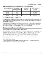
Page 34: ...into sockets of the back frame To adjust height move rubber grommets on the mounting posts to desired position Fig 104 105 Fig 106 Fig 107 Padded Headwing The padded headwing provides firm support for...

Page 35: ...lits in the back upholstery and attach at the back of the chair For added secure ment thread laces through the grommet holes in the upholstery and tie Fig 108 113 If the Occi Headwing is mounted to th...

Page 36: ...downward Fig 116 117 Adjustable Canopy Installation 1 Ali gn plasti c canopy retai ni ng cli ps wi th frame of the chai r Push on cli ps wi th the ball of your hand unti l they snap into place Fig 62...

Page 37: ...mobility base tubing Fig 120 121 Place bolt into hole of clamp and screw on using 5 32 Allen wrench Fig 122 123 NOTE The I V Pole can be removed or folded when not in use Fig 124 NOTE The I V pole ca...

Page 38: ...wards or outwards Fig 127 128 Make sure the lateral trunk supports are folded when you fold the chair Medial Thigh Support Abductor Separates thighs to improve hip alignment and stabilize sitting post...

Page 39: ...s the adductor flaps over the user s thighs 2 Wrap straps under and around the seat tube and at tach with the buckle under seat Fig 130 Fig 131 Fig 132 Attendant Hand Brake Tire Removal See Page 37 At...

Page 40: ...2 for opposite side Fig 135 4 To remove the anti tip tubes perform 1 3 steps in reverse order Fig 136 Caster Locks Push down to engage Caster Lock Push down to engage Caster Lock Push here to disengag...

Page 41: ...ing on wheel make sure the brake band is flush with the inside of the brake housing Tilt Brake Fig 141 Fig 142 Fig 143 Fig 144 WARNING Always make sure the wheels are installed properly You will hear...

Page 42: ...on underside of armrest until tray mount tube pops out 2 Grasp tray mount and extend until locked into position Fig 145 3 While holding the tray with both hands squeeze black handles and slide onto en...

Page 43: ...ion Fig 150 151 152 calf panel support Fig 150 Fig 151 Fig 152 The height adjustable flip up armrests provide added support and positioning Armrests flip up out of the way for easy access into the cha...

Page 44: ...rew at the top and 2 Velcro straps at the bottom The side panels will adjust to accommodate varying degrees of recline To adjust loosen the Velcro strap on the front outside of the panel recline the c...

Page 45: ...the legs out of ad duction and into better alignment which can provide for improved weight bearing balance and stability When used with a lap belt the 1 25mm anti thrust shelf in front of the ischials...

Page 46: ...ccupied chair unattended 2 With the material identification tag towards the rear of the chair place the cushion onto the seat upholstery Line up the Velcro straps to secure the cushion in place Front...

Page 47: ...elchair seat Make sure the cushion is firmly attached An improperly attached cushion may cause sliding potentially resulting in injury Changes in the user s condition or growth weight or changes in wh...

Page 48: ...See arrows in above photo for anchor points 4 The occupant restraints must include a lap and shoulder belt secured directly to the Rodeo frame and side or roof of the vehicle 5 Wheelchair restraint m...

Page 49: ...and the ease of use and proper fit of vehicle anchored belt restraints The letter designation reflects the overall rating of the lap and shoulder belt position Transportation Mode Instructions Using t...

Page 50: ...contact with vehicle components you must use both upper and lower torso belts WARNING Both pelvic and torso restraint belts must be used while travel ing aboard a motor vehicle WARNING Keep seatbelt r...

Page 51: ...ar zone is measured from the rearmost point on an occupant s head The front clear zone is measured from the frontmost point on an occupant s head Dimensions are shown in inches millimeters Fig 161 Sid...

Page 52: ...aps as illustrated in Fig 165 Your Convaid transit wheelchair can be easily secured by four point strap type tiedowns by attaching the hook end fittings of the tiedown straps to the four red securemen...

Page 53: ...EDOWN N STRAPS Fig 167 AND PREFERRED LOCATIONS OF FLOOR ANCHOR POINTS Fig 166 Fig 166 Fig 167 Fig 168 Fig 169 FIG 168 FRONT TIEDOWN STRAPS ANGLED AWAY FROM SIDES OF WHEELCHAIR FIG 169 CORRECT POSITION...

Page 54: ...E STANDARD METAL CLIP FIG 170 AT LOWER END OF SHOULDER BELT AND AT END OF OPTIONAL WHEELCHAIR ANCHORED LAP BELT USED TO CONNECT TO PIN BUSHING FIG 171 ON LAP BELT OR ON WHEEL CHAIR SECUREMENT POINT BR...

Page 55: ...located on the wheelchair s rear securement point brackets Fig 171 Before loading the wheelchair onto the vehicle lift fasten the lap belt over the wheelchair user s pelvis The wheelchair user should...

Page 56: ...der the user s elbows and pull the belt snug against the pelvis Ensure that belt webbing is not twisted as this may compromise safety It is best for Rodeo to be transported with the seat in a relative...

Page 57: ...dge of the tray and the wheelchair user or serious injury may result during a crash Convaid is a wheelchair manufacturer and does not offer wheelchair tiedown and occupant re straint systems WTORS How...

Page 58: ...be separated into plastic rubber steel aluminum etc and set aside for recycling 2 Intended Convaid s Rodeo is a lightweight non rigid high strength aluminum wheelchair with a tilt and recline mobilit...

Page 59: ...nt has outgrown it Do not ignore minor malfunctions and maintain the chair in good operating condition Monitor the wheel lock brakes regularly See maintenance chart If and whenever possible and feasib...

Page 60: ...ur Convaid product visually from time to time for possible wear and tear Teflon spray should be applied to frame and moving parts to maintain easy folding and adjustment a Tire Air Pressure The air pr...

Page 61: ...ant wipes regularly Keep frame dry and apply a non toxic hypoallergenic and biodegradable lubricant to all moving parts After longer storage periods and before further use the entire chair needs to be...

Page 62: ...eriods and before reuse the entire chair needs to be serviced cleaned and disinfected 8 Reuse Your Convaid chair should undergo a wipe down disinfection before reuse Please use a non tox ic biodegrada...

Page 63: ...l surface with enough momentum to travel six feet 2 m The chair should not veer to the left or right more than six inches 15 cm Wheels should be free running and the wheel lock brakes adjusted to adeq...

Page 64: ...ervice center together with a copy of the original invoice the Return Authorization Number and a written description of the problem THIS LIMITED WARRANTY EXCLUDES ANY CLAIM FOR INCIDENTAL OR CONSEQUEN...

Reviews: