

0471-0028-04
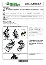
Figure 1-7 Unidrive SP size 2 DC connections
Figure 1-4 Fitting of the heatsink mounted braking resistor
•
Fit clip to heatsink in the position shown in diagram
opposite. Route the long cables of the resistor
assembly between the fins of the heatsink as
shown in the diagram opposite.
•
Fit the heatsink baffle plate in place with the cables
routed underneath. Ensure the cables are not
trapped between a heatsink fin and the baffle plate.
•
Fit the braking resistors to the heatsink. The
resistors are fitted with captive screws.
•
The screws should be tightened to a maximum
torque of 2.0 N m (1.5 lb ft).
•
Close the hinged fan baffle.
•
Fit cables to heatsink clip.
Figure 1-5 Connecting the brake resistor on a surface mounted drive
•
Fit the DC terminal cover grommets supplied in the
accessory box with the drive, to the cables.
•
Terminate the cables with suitable crimps and
connect to the BR and DC2 terminals.
•
Replace the terminal cover.
Figure 1-6 Connecting the brake resistor on a through-panel mounted drive
•
See section 3.10 in the
Unidrive SP User Guide
for
through-panel mounting cut-out details.
•
Pass the cables through the hole in the panel and
fit the hole grommet.
•
Fit the mounting bracket.
•
Fit the DC terminal cover grommets supplied in the
accessory box with the drive, to the cables. To
ensure a good seal, the grommets are a tight fit.
Lubrication may be required to help fit the
grommets to the cables.
•
Terminate the cables with suitable crimps and
connect to the BR and DC2 terminals.
•
Replace the terminal cover.
Failure to observe the following information may damage the resistor.
Parameter Settings
The Unidrive SP software contains an overload protection function for a braking
resistor. On Unidrive SP size 2 this function is enabled at default to protect the
heatsink mounted resistor. Below are the parameter settings.
For more information on the braking resistor software overload protection, see the
Unidrive SP Advanced User Guide
.
If the resistor is to be used at more than half of its average power rating then the
drive's cooling fan must be set to full speed by setting Pr
6.45
to On (1).
Resistor Specification
* To keep the temperature of the resistor below 70
°
C (158
°
F) in a 30
°
C (86
°
F) ambient, the
average power rating is 100W. The above parameter settings ensure this is the case.
Approvals
The resistor is UL recognised under UL file number E234469.
Route the cables
between these
two heatsink fins
2
BR
DC1 DC2
48V
-DC +DC
Internal
EMC filter
DC1 = -
DC2 = +
CAUTION
Parameter
200V Drive
400V Drive
Full power braking time
Pr
10.30
0.09
0.02
Full power braking period
Pr
10.31
2.0
Parameter
Value
DC resistance at 25
°
C
37.5
Ω
Peak instantaneous power over 1ms at nominal resistance
16kW
Average power over 60s
100W *
Ingress Protection (IP) rating
IP54
Maximum altitude
2000m


