


NOTE:
The back box wiring shown in this document is an example. Your
wire colors and functions may differ. If you are not sure which wires are
the Line In/Hot, Neutral, Load, and Earth Ground wires, have a trained
electrician perform the installation.
3
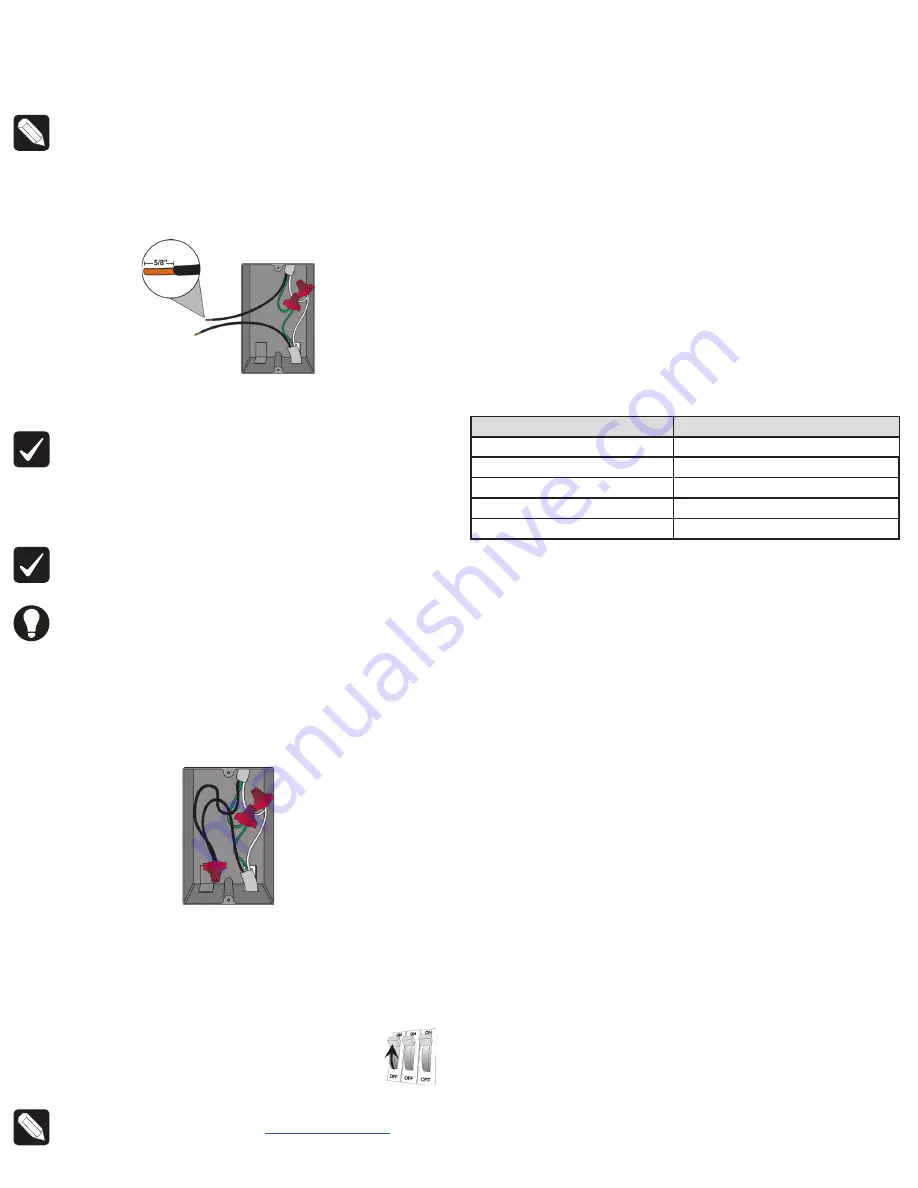
Prepare each wire. Wire insulation should be stripped back 5/8 of an inch
from the wire end (see Figure 1).
Figure 1.
Strip wire insulation
4
Identify your wiring application, and then see the appropriate wiring diagram
in the “Sample Wiring Configurations” section below.
IMPORTANT!
Not grounding this product as described in the section,
“Warnings and Considerations,” may result in an installation less immune
to damage caused by electrical disturbances, such as ESD or lightning,
and may void the warranty.
5
Identify and connect the dimmer wires to the back box wires using the wire
nuts.
IMPORTANT!
The yellow wire is not a traditional traveler. It cannot directly
power a lighting load. It must be used only to connect to a Control4
Auxiliary Keypad. See “Sample Wiring Configurations.”
TIP:
If you are using a Control4 push-on (screwless) faceplate in a multi-
gang installation, attach the black faceplate sub-plate to all of the devices
that will be installed into the wallbox prior to attaching the devices to the
wallbox. This will help ensure that all the devices are properly aligned and
on the same plane after installation.
6
Fit the wires back into the back box. Bend the wires in a zigzag pattern so
that they easily fold into the back box (Figure 2).
Figure 2.
Bend the wires
7
Align the dimmer to the back box (the load rating label should be at the
bottom) and fasten it with screws. Tighten the screws until the back side of
the yoke plate is even with the wall surface, but no further. Overtightening can
warp the dimmer and cause mechanical malfunction.
8
Install the Control4 Faceplate following the instructions in the
Faceplate
Installation Guide
or attach a standard Decora-style faceplate.
9
Turn ON power at the circuit breaker or replace the fuse
from the fuse box.
NOTE:
If the light flickers, adjust the dimmer’s max/min settings in
Composer (e.g. min 15%, max 85%). See
ctrl4.co/dimmersettings
.
Operation and configuration
On initial power up, all status LEDs on the dimmer will illuminate green indicating
that the device has power. To set up this dimmer for use with a Control4 system,
refer to the
Composer Pro User Guide
.
To operate this dimmer as a stand-alone device:
• Click
the
top button
to turn the light on.
• Click
the
bottom button
to turn the light off.
•
Press and hold the
top button
to ramp the light up. Release the button at the
desired light level.
•
Press and hold the bottom button to fade the light down. Release the button
at the desired light level.
Button tap sequences
The button tap sequences are defined in the table below. Button tap sequences
that require a single (1) button should use the top button.
Function
Button sequence
Identify
4
ZigBee channel
7
Reboot
15
Factory reset
9-4-9
Leave mesh and reset
13-4-13
Troubleshooting
If the light does not turn on:
•
Ensure at least one LED on the face of the dimmer is lit.
•
Ensure the light bulb is not burned out and is screwed in tightly.
•
Ensure that the circuit breaker is not turned OFF or tripped.
•
Check for proper wiring (see “Sample Wiring Configurations”).
•
For help on the installation or operation of this product, email or call the
Control4 Technical Support Center. Please provide your exact model number.
Contact [email protected] or see the web site www.control4.com.
Care and cleaning
•
Do NOT paint the dimmer or its wall plate.
•
Do NOT use any chemical cleaners to clean the dimmer.
•
Clean surface of the dimmer with a soft damp cloth as needed.
Legal and warranty information
Find details of the product’s Limited Warranty at
snapav.com/warranty
or request
a paper copy from Customer Service at
866.424.4489
. Find other legal resources,
such as regulatory notices and patent information, at
snapav.com/legal
.


