background image

In-Wall Touchscreen  

Wall Box - New Construction

Installation Guide

Introduction

This wall box kit provides a wall box (back box) to accommodate the installation 

of in-wall touchscreens. The kit is intended for new construction where drywall 

is not yet in place. Along with the wall box, the kit contains a stud plate for 

attachment to a wall stud before drywall installation.

Supported touchscreen models

•  C4-T4IW8-BL   

8" T4 In-Wall Touchscreen, Black

•  C4-T4IW8-WH  

8" T4 In-Wall Touchscreen, White

•  C4-T4IW10-BL   

10" T4 In-Wall Touchscreen, Black

•  C4-T4IW10-WH 

10" T4 In-Wall Touchscreen, White

Also supports these legacy touchscreens:

•  C4-WALL7 


T3-7 7" In-Wall Touchscreen

•  C4-WALL10 


T3-10 10" In-Wall Touchscreen

•  C4-TSWMC5-EG  

5" In-Wall Touchscreen

•  C4-TSWMC7-EG  

7" In-Wall Touchscreen

•  C4-TW7C0  


7" In-Wall Touchscreen with Camera

•  For more installation instructions specific to legacy touchscreens, see earlier 

versions of this guide.

Box contents

The following items are included in the kit:

•  In-Wall Touchscreen Wall Box - New Construction
•  Ferrite clamps: two rectangular, one round
•  Plastic wall boxes include two screws. Metal wall boxes include four screws  

(2 short, 2 long)

Tools needed

•  Tape measure and pencil
•  Hammer or screwdriver
•  A 5/16" nut driver or socket wrench (metal wall box only)
•  Nails or screws (4 to 6)

Warning! 

Before you install the wall box, ensure that you’ve turned off the 

power to the wires that will be attached to the box.

Attention !

 Avant d’installer le boîtier arrière, assurer vous d’avoir désactivé le 

pouvoir sur les fils qui seront attachées à la boîte.

Specifications

Dimensions: 68 x 104 x 81 mm (2.7 x 4.1 x 3.19")

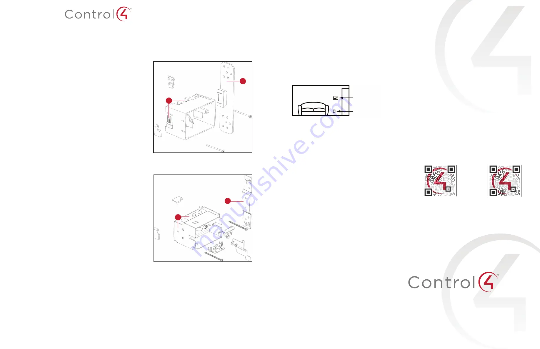
Plastic wall box model (C4-NWB57C-P)

Dovetail socket (on both sides to reverse position)

Stud plate

B

A

Metal wall box model (C4-NWB57C-M)

Mounting location (on both sides to reverse position)

Stud plate

B

A

Installing the wall box

Note: 

This kit is intended for installation of a wall box before drywall 

installation. If the drywall is in place, use kits intended for retrofit (C4-

RWB57C-P or C4-RWB57C-M). For more information, visit the product pages 

at 

ctrl4.co/boxnewp

 and 

ctrl4.co/boxnewm

To install this wall box:

Find an appropriate wall box location for the touchscreen you are installing: 

•  The wall box should be in a convenient location, for example, near the 

entrance of a room.

•  The wall box should be at eye level, about about 1.5 meters (57 to 

61 inches) from the floor.

Touchscreen

AC outlet (unless 

using PoE)

•  When using Ethernet or PoE, the wall box should be near a location where 

an Ethernet Cat 5/6 cable is pulled.

•  When using AC power, position the wall box above or near an AC power 

source, such as an AC outlet.

Hold the wall box and stud plate against the nearest stud, then mark the 

correct position according to your choices in Step 1. Follow these guidelines:

Place the wall box so that, when mounted, it is flush with the surface of 

the drywall after the drywall is installed. For example, if the drywall is 

3/8 of an inch deep, the front rim of the wall box must be 3/8 of an inch 

above the wall stud (toward you).

Important: 

Make sure the wall box is flush with the wall after the drywall 

is installed. Allow 3/8 of an inch before the drywall is installed (depending 

on the thickness of the drywall), and err toward 5/16 inch for the best fit. 

Install the wall box according to the arrows inside the box that indicate 

the correct side up.

Important: 

For safety, install the wall box with the correct side up.

Install the wall box with the stud plate on either the right or the left side, 

depending on which wall stud you choose. You may detach the stud plate 

from the wall box on one side and reattach it on the opposite side, if 

needed.

Detach the stud plate from the wall box.

•  Plastic box: Slide the wall plate toward the back of the wall box.
•  Metal box: Unscrew the wall box from the stud plate.
This allows you to attach the stud plate to the wall stud without interference 

from the wall box.

Align the stud plate with the marks you made on the stud (Step 2). If you are 

using a plastic wall box, make sure the dovetail is toward the back of the stud 

plate (away from you).

Nail or screw the stud plate to the wall stud.  

Recommended hardware: #9/3.5 mm wood screw or 6D/3 mm nail.

Mount the wall box to the stud plate.

•  Plastic box: Slide the wall box onto the stud plate dovetail all the way, 

leaving the wall box protruding the depth of the drywall, or slightly less 

(Step 2a).

•  Metal box: Bolt the wall box back onto the stud plate.

Note: 

If you are using a metal box, you can continue to adjust its angle 

and position slightly relative to the drywall.

When running cables into the wall box, use a left-side knockout for the 

Ethernet cable, and use a right-side knockout for the AC power (if used).

Note: 

The left (low-voltage) and right (high-voltage) sides of the wall box are 

separated by a barrier. Low-voltage connections must be pulled through a 

knockout on the left side, and high-voltage on the right.

Caution: 

Use only 14 AWG wire for AC connections. For supply connections, 

use wires suitable for at least 60 °C (140 °F).

Install the drywall as you would normally, making sure to cut the size of the 

hole accurately.

After you install the drywall, carefully tighten the screws to pull in the 

securing tabs so that the wall box is flush with the surface of the wall.

Important: 

In the metal wall box kit, the two longer screws are for use 

with the T4, the shorter for use with the T3.

Note: 

Overtightening the screws may pull the box into the wall.

Important: 

When you are ready to install the drywall, and you are cutting the 

opening for the wall box, 

do not 

cut the opening too large. Be conservative 

and enlarge the hole as needed.

Additional resources

The following resources are available for additional support.

•  Knowledgebase and forums in Technician Community
•  Technical Support
•  Control4 website: 

www.control4.com

•  Composer documentation in its online help.

Warranty and legal notices

Find details of this product’s 2-Year Limited Warranty at 

snapav.com/warranty

, or 

request a paper copy from Customer Service at (866) 424-4489. Find other legal 

resources, such as regulatory notices and patent information, at 

snapav.com/legal

.

More help

For the latest version of this document, open this URL or scan the QR code on a 

device that can view PDFs.

200-00165-J 

2020-10-20 MS

J

Copyright ©2020, Wirepath Home Systems, LLC. All rights reserved. Control4 and Snap 
AV and their respective logos are registered trademarks or trademarks of Wirepath 
Home Systems, LLC, dba “Control4” and/or dba “SnapAV” in the United States and/or 
other countries. Snap AV and Wirepath are also registered trademarks or trademarks of 
Wirepath Home Systems, LLC. Other names and brands may be claimed as the property 
of their respective owners. All specifications subject to change without notice.

MOST RECENT VERSION

ctrl4.co/

wallbox-new

T4 IN-WALL TOUCHSCREEN INSTALL GUIDE

ctrl4.co/

t4-inwall-ig

Summary of Contents for C4-T4T10-BL

Page 1: ...EC Caution Do not place the touchscreen near sources of heat or expose to direct sunlight for an extended time Avertissement Ne placez pas l unité près des sources de chaleur ou exposition pour diriger la lumière du soleil pendant une période prolongée Caution This product generates heat The room must have adequate ventilation or the ability to dissipate heat effectively Avertissement Ce produit p...

Page 2: ...66 mm 4 53 4 02 2 60 Weight 8 Touchscreen 1 05 lb 0 47 kg 8 Charging base 1 4 lb 0 64 kg 10 Touchscreen 1 35 lb 0 60 kg 10 Charging base 1 05 lb 0 46 kg Operating temperature 0 to 40 C 32 to 104 F Storage temperature 20 to 70 C 4 to 158 F Requirements A controller fully installed and configured with Control4 OS 3 2 1 or newer A wireless network IEEE 802 11b g n must be installed and available with...

Page 3: ...address follow the instructions under To set a wireless static IP address below before proceeding 5 Tap Connect If you don t see the network you want 1 Tap then tap the Network SSID field and type the SSID name of the network by using the on screen keyboard 2 Tap the Security field then select the type of security to use 3 Tap the Password field then use the on screen keyboard to type the password...

Page 4: ...ightly rotate the touchscreen while lifting it Permanent mount You can mount a touchscreen permanently to a surface such as a table using the optional T4 Tabletop Permanent Mount Kit C4 T4PMNT 1 Peel off the plastic cover on the touchscreen s docking connector recess 2 Use the Phillips head flat screws provided in the kit to install the permanent mount adapter into the touchscreen s docking connec...

Page 5: ...een 1 Press and hold the power button for several seconds until the touchscreen turns off 2 Press and release the power button again to turn on To perform a factory data reset 1 On the touchscreen s main screen tap Settings System Info then Factory data reset OR If the touchscreen has not yet been configured tap About then Factory data reset OR To reset without using the display screen a Dock the ...

Page 6: ...l More help For the latest version of this document open this URL or scan the QR code on a device that can view PDFs 200 00683 A 2020 10 09 MS Copyright 2020 Wirepath Home Systems LLC All rights reserved Control4 and Snap AV and their respective logos are registered trademarks or trademarks of Wirepath Home Systems LLC dba Control4 and or dba SnapAV in the United States and or other countries Snap...

Page 7: ... no additional network wiring is needed AC power is used to power the touchscreen Note 802 11b is not recommended for video intercom We recommend using Wireless N See Specifications and Power and Network Installation Options for more information Box contents 8 or 10 T4 In Wall Touchscreen Power box to power the touchscreen Two screws to attach the power box to the wall box Set screw to secure the ...

Page 8: ...d aucun dommage encouru avec l abus de ce produit Voyez que Warranty Specifications and requirements Specifications Model Numbers C4 T4IW10 BL C4 T4IW10 WH C4 T4IW8 BL C4 T4IW8 WH Screen Resolution 1920 1200 capacitive touch Camera 720p Network Ethernet or Wi Fi 802 11b g n 2 4 GHz 802 11a n ac 5 GHz Security WEP WPA WPA2 PSK 802 1x EAP PEAP Notes 1 While technically the touchscreen can use 802 11...

Page 9: ...tant The top of the touchscreen must be mounted no higher than 2 m 6 6 ft above the floor Figure 1 Touchscreen placement LED indicator The LED on the touchscreen indicates the camera status of the camera and booting information as described in the next table Camera LED color state Touchscreen status Off Camera is off Green Camera is on Green blinking slowly Touchscreen is booting Installation Warn...

Page 10: ... Fi network when already connected by Ethernet Notes 1 Video Intercom Although this device supports 802 11b g n 802 11 b is not recommended for Video Intercom use 2 We recommend Wireless N for Video Intercom See the Composer Pro User Guide for details about the touchscreen s properties Wireless Network Limitations Many Wi Fi Access Points handle Multicasts Wi Fi simultaneously sent to multiple dev...

Page 11: ... wires to each terminal Figure 5 then tighten the screws Figure 6 Connect AC power to terminal block Neutral N Line L 4 If using a plastic wall box with an exposed bare copper ground wrap the ground in electrical tape or heat shrink tape tubing If using a metal wall box attach the ground wire to the wall box Attach the power box and touchscreen To attach the power box and touchscreen 1 Align and b...

Page 12: ... at a time and use the on screen keyboard to type the IP Address Gateway Netmask DNS 1 preferred and DNS 2 alternate 5 Tap SAVE when finished Add and configure in Composer Pro After the touchscreen is installed and appears on the home network use Composer Pro to add it to the Control4 system and configure it Use the Composer Pro System Design and Connections views to add and configure this device ...

Page 13: ...ds until the touchscreen turns off 2 Press and release the power button again to turn back on To restore to factory defaults 1 On the touchscreen s main screen tap Settings System Info then Factory data reset OR If the touchscreen has not yet been configured tap About then Factory data reset OR To reset without using the display screen insert a straightened paper clip into the left pinhole on top ...

Page 14: ... of this document open this URL or scan the QR code on a device that can view PDFs 200 00678 B 2020 10 20 MS Copyright 2020 Wirepath Home Systems LLC All rights reserved Control4 and Snap AV and their respective logos are registered trademarks or trademarks of Wirepath Home Systems LLC dba Control4 and or dba SnapAV in the United States and or other countries Snap AV and Wirepath are also register...

Page 15: ...at indicate the correct side up Important For safety install the wall box with the correct side up c Install the wall box with the stud plate on either the right or the left side depending on which wall stud you choose You may detach the stud plate from the wall box on one side and reattach it on the opposite side if needed 3 Detach the stud plate from the wall box Plastic box Slide the wall plate...

Page 16: ...rtures de ventilation Installer conformément aux instructions du fabricant 8 Do not install near any heat sources such as radiators heat registers stoves or other apparatus including amplifiers that produce heat Ne pas installer près de sources de chaleur telles que des radiateurs registres de chaleur poêles ou autres appareils incluant les amplificateurs qui produisent de la chaleur 9 Do not defe...

Page 17: ...t doit être effectué par un électricien certifié Pour les connexions d alimentation utilisez uniquement 14 AWG qui convient à au moins 600C Cet équipement doit être monté à une hauteur inférieure ou égale à 2 m Cet équipement ne peut être utilisé qu avec l un des modèles de boîtiers muraux certifiés séparément suivants C4 NWB57C M C4 NWB57C P C4 RWB57C M C4 RWB57C P 14 Refer all servicing to quali...

Page 18: ...ts de tension dangereux ou court circuiter des pièces qui pourraient entraîner un incendie ou un choc électrique 19 This product can interfere with electrical equipment such as tape recorders TV sets radios computers and microwave ovens if placed in close proximity Ce produit peut interférer avec des appareils électriques tels que les magnétophones téléviseurs radios ordinateurs et fours à micro o...

Page 19: ...equipment into an outlet on a circuit different from that to which the receiver is connected Consult the dealer or an experienced radio TV technician for help This device complies with part 15 of the FCC rules and ISED s license exempt RSSs Operation is subject to the following two conditions 1 This device may not cause harmful interference and 2 this device must accept any interference received i...

Page 20: ... primary users i e priority users of the bands 5650 5850 MHz and that these radars could cause interference and or damage to LE LAN devices Avertissement i les dispositifs fonctionnant dans la bande 5150 5250 MHz sont réservés uniquement pour une utilisation à l intérieur afin de réduire les risques de brouillage préjudiciable aux systèmes de satellites mobiles utilisant les mêmes canaux ii le gai...

Page 21: ...radiations RF Cet équipement est conforme aux limites d exposition aux rayonnements RF et IC de la FCC définies pour un environnement non contrôlé Cet équipement doit être installé et utilisé avec une distance minimale de 20 centimètres entre le radiateur et votre corps ou des personnes proches Europe Compliance Compliance of this equipment is confirmed by the following logo that is placed on the ...

Page 22: ...eting all requirements of the Waste Electrical and Electronic Equipment WEEE directive 2012 19 EC The WEEE directive requires the manufacturers of electrical and electronic equipment who sell in EU countries 1 label their equipment to notify customers that it needs to be recycled and 2 provide a way for their products to be appropriately disposed of or recycled at the end of their product lifespan...

Reviews: