


2
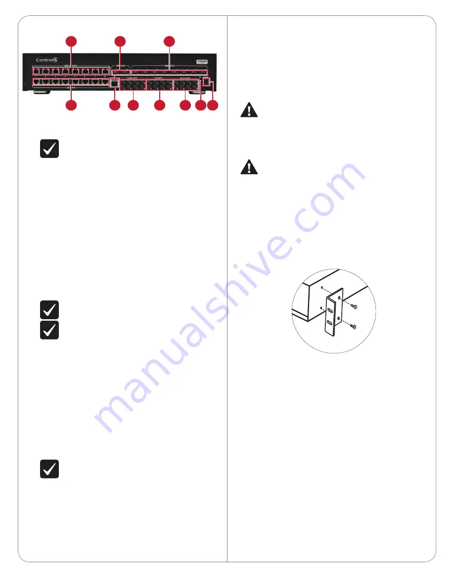
Back Panel
A
HDBT OUTPUTS—Connect a HDBaseT Receiver (C4-HDBTE-B)
to these ports. Carries video, audio, Internet, and commands over
CAT5e/6 cable.
IMPORTANT!
Cable length cannot exceed 328 feet (100
meters) from switch to receiver.
B
HDMI OUTS—Connect HDMI-compatible playback devices to these
ports. These are shared outputs for zones 7 and 8 (using HDMI OUT
7 and 8, respectively). Zones 7 and 8 can
either
be HDBT
or
HDMI
out (not both at the same time).
C
HDMI INPUTS—Connect HDMI sources (audio, video, or both) to
these ports.
D
LAN PORTS—Connect Ethernet-compatible playback or network
devices to these ports. These port numbers correspond to the
HDBT OUTS. There is a one-to-one input to output on the HDBaseT
Receiver. Any of these ports in use needs to be connected to a
network switch. On the receiver side, they will connect the LAN
port to the device or network switch.
E
IP control port—Connect the home network (via a router or
Ethernet switch) to this port.
F
AUDIO OUTS—Connect 1/8" (3.5 mm) plug-compatible audio
switches or amplifiers to these ports. These are a mirrored output
of the stereo audio for the respective zone. (The stereo audio
occurring in zone 1 [the HDBaseT Receiver connected to HDBT
port 1] will also occur in the analog stereo output 1.)
NOTE:
These are stereo only. Multi-channel audio will not
play out of these ports.
IMPORTANT!
Audio cable length should not exceed 10 feet
(about 3 meters).
G
IR PORTS (pass-through)—Allow 38kHz IR data to be passed from
a controller to an HDBaseT Receiver, or from an HDBaseT Receiver
to the switch. Uses standard 1/8” (3.5 mm) IR cable.
• When a controller is connected to the switch’s IR port, a stereo
mini jack cable must be used.
• When an IR emitter is connected to the switch or the HDBaseT
Receiver, it must be the mono mini-jack emitter (available from
Control4).
• If the IR is going from the receiver to the switch, then the
capture device connected to the receiver must be an IR receiver
and
cannot
be a Control4 controller.
H
RS-232 PORTS—Allow control to be sent from a controller to the
output of an HDBT Receiver. They can be used with a 1/8” (3.5 mm)
accessory cable (C4-CBL3.5-DB9B). If connecting to the serial
ports on an HC-250, you can use a stereo 3.5 mm-to-3.5 mm cable.
These port numbers correspond to their respective zone output.
IMPORTANT!
Serial cable length should not exceed 10 feet
(about 3 meters).
I
ID button—Press to identify the device for Composer Pro system
setup.
J
Power Port—Connect the included power adapter here. Use only
the included power adapter. (DIN, 12VDC) When connecting, slide
back the locking connector and orient the plug flat side down.
Installation
Essential setup tasks include:
1
Disconnecting power to the switch
2
Installing the rack-mount bracket
3
Connecting the input and output devices
4
Connecting the device to the network and power
5
Setting up the connections in Composer Pro
WARNING!
Disconnect power to the switch and connected
devices while making connections. Reconnect power only when
the connections are complete.
ATTENTION !
Coupez l’alimentation à l’interrupteur et les
périphériques connectés lors des connexions. Rebranchez
uniquement lorsque les connexions sont terminées.
CAUTION!
Do not run HDBaseT/Zone CAT5e/6 cabling with
or in close parallel proximity to mains power cables, or severe
signal interference may result.
ATTENTION !
N’installez pas le câblage HDBaseT / Zone
CAT5e / 6 avec ou à proximité immédiate parallèle à un câbles
d’électricité, ou des interférences de signaux graves peuvent en
résulter.
Installing a Rack-mount Bracket
1
Align the holes on each bracket with the holes on the HDMI switch,
then mount the brackets using four (4) 8-32 x 3/8” flat-head screws
(included).
Connect Input and Output Devices
Refer to any device-specific documentation for additional installation
instructions.
To connect:
1
Connect the source devices to the
HDMI INPUTS
and other inputs.
Each numbered input connection associates to the same HDBT
port.
Example:
The HDMI INPUT #1, IR PORT #1, and RS232 PORT #1
ports all associate with the HDBT OUTPUT #1 port.
2
When connecting a controller to the HDMI switch via RS-232:
a.
If connecting an HC800, use a 1/8” (3.5 mm) accessory cable
(C4-CBL3.5-DB9B).
b.
If connecting an HC250, use a stereo 3.5 mm-to-3.5 mm cable.
3
Connect the
HDBT OUTPUT
port to the
HDBASET INPUT
port on
the HDBaseT Receiver (C4-HDBTE-B).
4
Connect the appropriate
LAN
,
IR
, and
RS-232
serial connections
from the receiver to the display device (such as a TV, receiver, or
projector).
For RS-232, the switch/receiver combination is configured as a null
modem. Consequently, you may not need a null modem cable or
adapter if the display device usually requires one.
C
B
A
D
E
F
G
H
I J


