Non-Overhaul Removal and Replacement
Teledyne Continental Motors, Inc.
TM
10-56
IOF-240 Series Engine Maintenance Manual
29 November 2006
10-11.
FADEC Component Removal and Installation
10-11.1. ECU or SSA Connector Installation
NOTE: If damage is evident to the EMI gaskets or environmental
seals on the 50-pin ECU connectors or the 25-pin SSA connectors,
replace the damaged gaskets or seals.
Procedure
1.
Disconnect electrical power to the engine; cut and remove the connector cable tie. Cut
and remove safety wire from securing screws. Fully disengage the connector securing
screws.
2.
To remove the connector(s) firmly grasp the edges of the connector back shell and
pull the connector away from the unit.
NOTE: The engine low voltage harness connector fasteners are
captive in the back shell and cannot be removed from the
connector.
WARNING
Do not separate the connector(s) from the unit by pulling on
the harness leads. Pulling on the harness leads can cause
permanent, irreparable damage to the engine low voltage
harness which may result in engine malfunction.
3.
Remove the EMI gasket and environmental seal.
4.
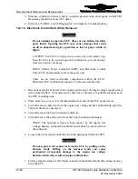
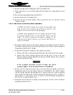
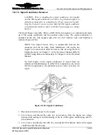
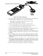
Using a Scotch-Brite pad, clean the connector back shell contact area immediately
surrounding the header shell on the ECU or SSA Conditioner (Figure 10-46 and
Figure 10-47).
Header
Shell
50 pin
connector
Header
Shell
50 pin
connector
Figure 10-46.
Typical ECU 50-pin Connector


