


Form No. R92.00 Rev. 10/03
2
PLUMBING (continued...)
Hydraulic fluid from the case drain line should be
returned to the reservoir below the fluid level, and as
far from the supply intake as possible. All fluid lines
(whether pipe, tubing or hose) must be of adequate
size and strength to assure free flow through the
pump. Do not tee return lines together.
SYSTEM RELIEF VALVES
Although HPV series pumps have a very fast off-
stroke compensator response, fast acting relief valves
are recommended in all cases for safety. They also
help reduce transient pressure spikes.
RECOMMENDED FLUID
Note: The following fluid recommendations
and specifications apply to HPV series
pumps only. Assure that all other
components in the hydraulic system have
compatible requirements.
Petroleum-based, and most phosphate esters. Fluids
should be designated by the manufacturer for use in
hydraulic systems. Fluids should be formulated with
oxidation inhibitors, anti-rust, anti-foam and
deaerating agents. Other fluids may be acceptable,
but special O-rings may be required. Nitrile (Buna)
seals are standard.
VISCOSITY
Maximum at full power . . . . . . .750 SUS (160 Cst)
Optimum for maximum life . . . .140 SUS (30 Cst)
Minimum at full power . . . . . . . 60 SUS (10 Cst)
VISCOSITY INDEX
90 V.I. minimum. Higher values extend the operating
temperature range, but may reduce fluid service life.
Fluid Operating Temperature – Operating
temperature should be determined by the viscosity
characteristics of the fluid used. Fluid temperature in
the reservoir during operation should be kept between
100° F. and 130° F. (38° C. and 54° C.) Because high
temperature degrades seals, reduces service life and
creates hazards, fluid temperature should not exceed
180° F. (82° C.) at the case drain.
CAUTION – Fluid temperatures in excess of
120° F. (49° C.) can cause serious burns and
scalding. Allow fluid to cool before
performing any repairs or maintenance.
Fluid Cleanliness – Control particle contamination by
changing or cleaning all filter elements periodically
BEFORE they become clogged and start to by-pass.
Fluid must be cleaned before and continuously during
operation to a cleanliness level of ISO 18/16/13 or
better. This level of cleanliness can usually be
accomplished by use of 10 micron filters. Better fluid
cleanliness will significantly extend component life.
Since contaminant generation varies with each
application, each must be analyzed to determine
proper filtration to maintain required cleanliness.
After Extended Shutdowns – Some types of
hydraulic fluids become tacky after long periods of
non-use. If possible, hand turn the pump several
times after extended shutdowns to assure that all
components move freely before powering up.
CAUTION – Before hand turning any pump,
be sure that any resulting machine function
will not endanger persons or equipment.
PREVENTIVE MAINTENANCE
This pump is self-lubricating. Preventive maintenance
is limited to keeping the system fluid clean by
changing filters regularly. Since filtering needs can
vary depending on applications, filters used with this
pump should be equipped with indicators that show
when changes are needed. Do not operate the pump
in a system with clogged or bypassing filters.
Keep all fittings and screws tight. Do not operate this
pump at pressures or speeds in excess of stated
limits. If the pump does not operate properly, check
the Trouble Shooting Section of this manual before
attempting to overhaul the pump.
Overhauls are relatively simple, and are covered in
the Repair Procedures Section of this manual.
Note: It is especially important to keep
suction or inlet piping and fittings tight
and in good repair. Air drawn into the
system through loose or damaged intake
fittings can cause the pump to fail.
START UP PROCEDURE FOR NEW INSTALLATION
1. Read and understand the Service Manual. Identify
components and their
functions.
2. Visually inspect system
components and lines for
possible damage.
3. Check reservoir for
cleanliness. Drain and
clean as required.
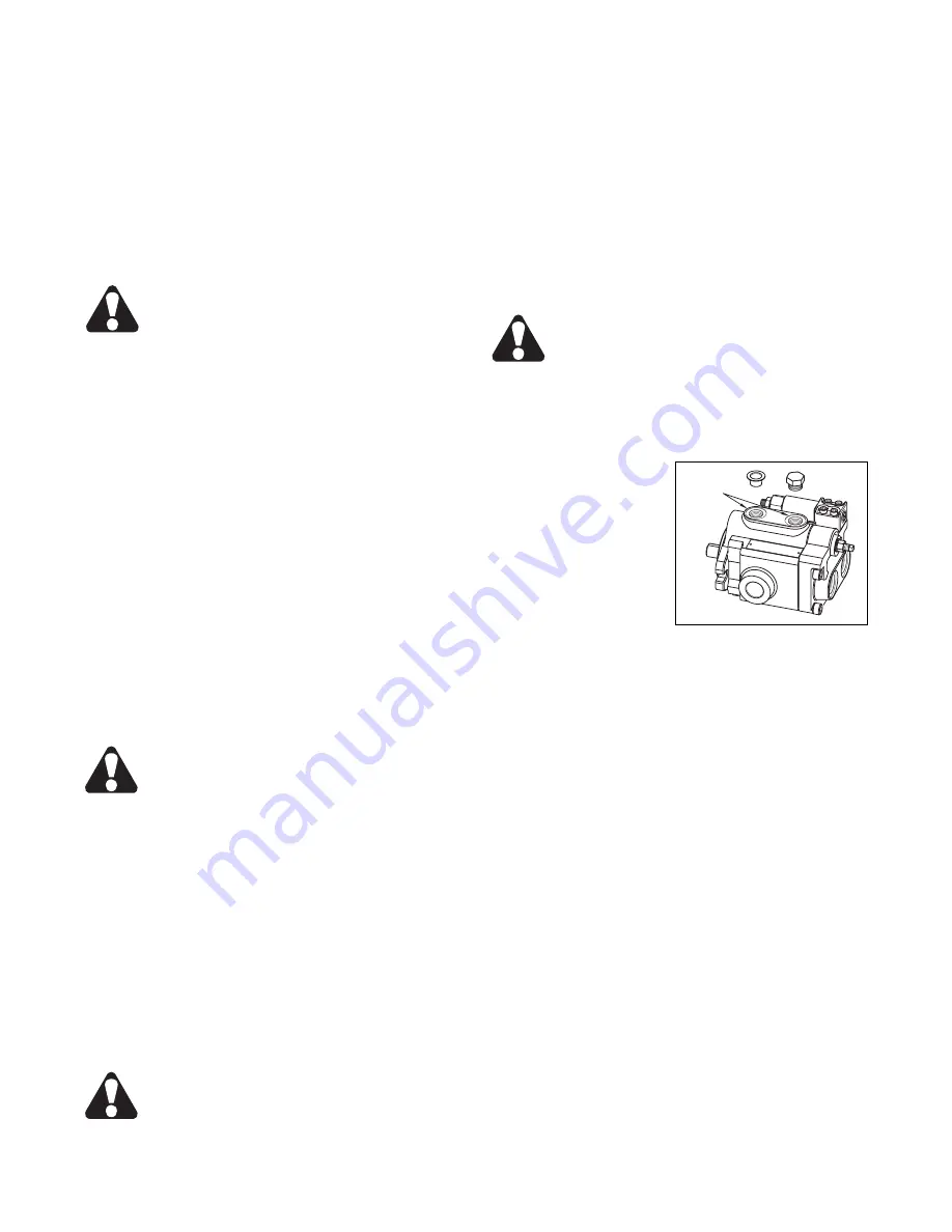
4. Check reservoir fluid
level and fill as required
with filtered fluid that
meets or exceeds ISO 18/16/13 cleanliness level. Fill
pump through either Case Drain Port (Figure 3).
5. Check drive alignment.
6. Check and activate oil cooler (if included in circuit).
Check fluid temperature.
7. Reduce relief valve pressure settings. Make sure
accurate pressure readings can be made at
appropriate places.
8. If the system includes solenoids, check for proper
actuation.
9. Jog electric motor to confirm proper rotation.
Jogging the electric motor primes the pump and
bleeds air from the system.
10. Start pump drive. Look for leaks, and listen for
excessive noise at the pump. If leaks, chattering or
other noises are observed, immediately turn the pump
off. Corrective actions are covered in the Trouble
Shooting Section.
11. Cycle unloaded machine at low pressure, and
observe actuation (at low speed, if possible).
12. Increase pressure settings gradually. Check for
leaks in all lines, especially in the pump inlet line.
13. Adjust system pressure as needed.
14. Gradually increase system speed to normal
operating level. Be alert for trouble as indicated by
noise, sound changes, system shocks, leaks, or air
bubbles in the reservoir.
Case Drain
Ports
Figure 3


