


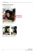


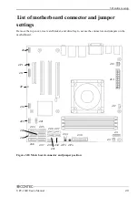
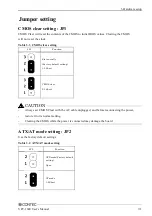
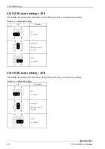


3. Hardware setup
VPC-1600 User’s Manual
37
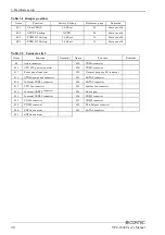
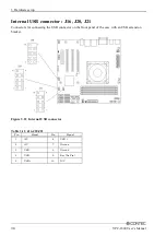
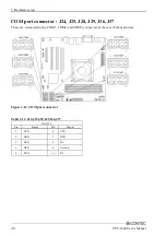
Front panel connector : J11
A connector for connecting the power switch, reset switch, power LED, HDD LED, etc. at the front of
the case.For the VPC-3000 series, they are already connected on the front panel by a special cable.
Figure 3.23 Front panel connector
Table 3.13 J11
Pin
Signal
Pin
Signal
1
P)
9
LAN2_LINK
2
S)
10
Power On(-)
3
PWR_LED(-)
11
LAN2_ACT
4
N/C
12
Power On(+)
5
LAN1_ACT
13
H)
6
N/C
14
Reset(+)
7
LAN1_LINK
15
HDD_LED(-)
8
Speaker(-)
16
Reset(-)
Summary of Contents for VPC-1600
Page 1: ...FA Computer Space Saving Model VPC 1600 User s Manual CONTEC CO LTD...
Page 15: ...1 Before Using the Product 8 VPC 1600 User s Manual...
Page 21: ...2 System reference 14 VPC 1600 User s Manual...
Page 49: ...3 Hardware setup 42 VPC 1600 User s Manual...
Page 69: ...4 BIOS setup 62 VPC 1600 User s Manual...
Page 97: ...6 Software RAID Setup 90 VPC 1600 User s Manual...