3. Connecting to an External Device
ADI16-4(FIT)GY
11
3.
Connecting to an External Device
Interface Connector
How to Connect an Interface Connector
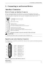
When connecting the Module to an external device, you can use the supplied connector plug.
To wire each terminal, strip the wire about 9 to 10 mm from the end and insert it into the opening.
After inserting the wire, tighten the screw to fasten it. Compatible wires are AWG 28 to 16.
Figure 3.1. Connecting an interface connector and connectors that can be used
Removing the connector plug by grasping the cable can break the wire.
Signal Layout on the Interface Connector
The Module can be connected to an external device using a 12-pin (1 group) connector that is provided
on the Module face.
Figure 3.2. Signal layout on the interface connector
CAUTION
12
11
10
9
8
7
6
5
4
3
2
1
CH0 [+]
CH0 [-]
AG
CH1 [+]
CH1 [-]
AG
CH2 [+]
CH2 [-]
AG
CH3 [+]
CH3 [-]
AG
Analog Input 0ch [+]
Analog Input 0ch [-]
Analog Ground
Analog Input 1ch [+]
Analog Input 1ch [-]
Analog Ground
Analog Input 2ch [+]
Analog Input 2ch [-]
Analog Ground
Analog Input 3ch [+]
Analog Input 3ch [-]
Analog Ground
CH0
CH1
CH2
CH3
+
-
AG
+
-
AG
+
-
AG
+
-
AG

