Contec CT 250 Antrieb Instruction Manual Download Page 5

Betriebsanleitung / Manual CT 250 Antrieb / Drive Unit         - 5 - 


CONTEC 

Maschinenbau

 & Entwicklungstechnik GmbH 


© CONTEC

®

 2018 

Hauptstrasse 146, 57518 Alsdorf (Sieg) / Germany 
Tel: +49 (0) 2741 9344-0   Fax: +49 (0) 2741 9344-29 


f      Die  Vorschubgeschwindigkeit  langsam 
mittels 

des 

Potentiometers 

auf 

die 

gewünschte Geschwindigkeit einstellen. 


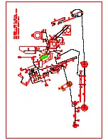
g  Es  ist  auch  möglich  mit  der  Fräse  ohne 
Antrieb  zu  arbeiten.  Dazu  muss  der  Hebel 
Höhenschnellverstellung  (Anhang  Skizze 
Pos  171)  hochgezogen  werden.  An  der 
Liftstange  an  welcher  der  Antriebsmotor 
angeflanscht    ist  (Anhang  Skizze  Pos  183) 
befindet  sich  ein  Stift  an  einer  Kette.  Dieser 
Stift muss unterhalb der Liftstange zwischen 
die  Gabeln  des  Gelenks  gesteckt  werden. 
Beim  Herabsetzen  der  Maschine  mit  dem 
Hebel  Höhenschnellverstellung  findet  jetzt 
kein 

Kraftschluss 

zwischen 

den 

Vorschubwalzen  (Anhang  Skizze  Pos  187) 
und den Hinterrädern mehr statt. 


h  Starke  Staubentwicklung  kann  durch 
Anschluß  einer  Absauganlage  vermieden 
werden. 
 

Die 

Dämpfung 

des 

Bedienergriffs 

ermöglicht ein fast vibrationsfreies Arbeiten 


f  Increase the drive speed of the machine by 
slowly  turning  the  potentiometer  up  to  the 
required speed. 


g  It  is  also  possible  to  operate  the  planer 
without the drive unit. Therefore the lever of 
the  height  adjustment  (Appendix  diagram 
No.  171)  must  be  brought  to  its  upper 
position.  On  the  lifting  bar,  to  which  the 
drive  motor  is  fixed  (Appendix  diagram  No. 
183)  a  pin  on  a  chain  is  attached.  This  pin 
must  be  pushed  into  the  gap  in  between  the 
bottom  of  the  lifting  bar  and  the  joint  of  the 
rear  wheel  swing.  By  lowering  the  machine 
with  the  lever  of  the  height  adjustment  the 
pin will prevent  the drive wheels (Appendix 
diagram  No.  187)  from  being  connected  to 
the rear wheels of the planer.  
 
h  A  dust  free  operation    can  be  achieved  by 
connecting a dust collector to the dust port. 
 
 
i The vibration damped handle bar ensures an 
easier operation. 


4 Wechsel der Diamanttrommel 


4 Changing the diamond drum


Achtung:

  Vor  Wartungsarbeiten  Motor  zum 

Stillstand bringen. Netzstecker ziehen. 


-


Maschine 

hochdrehen, 

damit 

die 

Werkzeuge vom Boden abgehoben sind 

 
-


Schrauben am rechten Seitendeckel lösen 
(M10, Schlüsselweite 17 mm) 

 
-


Rechten 

Seitendeckel 

vorsichtig 

abziehen. 

 
-


Diamanttrommel  herausziehen.  Diamant-
blätter  (siehe  Anhang  Explosionszeich-
nung  Diamanttrommel)  auf  Verschleiß 
prüfen.  Trommel  selbst  auf  Verschleiß 

 
Attention:

  Before  any  maintenance,  the 

machine must be brought to a complete stand 
still.  Always  disconnect  the  machine  from 
the mains. 
 
-


Lift the machine with the lever so that the 
tools are well clear of the floor. 

 
-


Unscrew  the  screws  on  the  right  side 
plate (M10, Key width 17 mm) 

 
-


Carefully remove the side plate. 


-


Take  out  the  diamond  drum.  Check  the 
blades  of  the  diamond  drum  (Appendix 
diagram diamond drum) if they are worn 
out.  Also  check  the  drum  itself.  If 

Summary of Contents for CT 250 Antrieb

Page 1: ...50 Antrieb Bodenfräsmaschine Floor Planer Betriebsanleitung Originalausgabe Instruction manual Original edition Ergänzende Betriebsanleitung für den Antrieb Additional Instruction manual for the drive unit ...

Page 2: ...dorf Sieg Germany Tel 49 0 2741 9344 0 Fax 49 0 2741 9344 29 Inhaltsverzeichnis 1 Technische Daten Technical data 3 1 1 Antrieb Drive unit 3 1 2 Werkzeuge Tools 3 2 Einsatzgebiete der Werkzeuge Applications of the tools 3 3 Inbetriebnahme und Fräsen Operating 4 4 Wechsel der Diamanttrommel Changing the diamond drum 5 5 Anhang Appendix 6 ...

Page 3: ...durchmesser 57 Anzahl Lamellen 132 Anzahl Walzenfräser 48 Anzahl Stahllamellen 540 Diamanttrommel Trommeldurchmesser 200 mm Maximale Anzahl der Diamantblätter 60 Drum 180 mm Drum shaft 16 mm Number of shafts 6 TCT Cutter 57 6 Milling cutter 57 20 Beam flails 57 Cutter 57 Number of TCT cutters 132 Number of milling cutters 48 Number of beam flails 540 Diamond drum Drum 200 mm Max number of diamond ...

Page 4: ...ögliche Tiefeneinstellung ist von der Härte des Bodens abhängig und muss von Fall zu Fall ermittelt werden Achtung Der Motor der Fräse darf niemals eingeschaltet werden wenn die Werkzeuge noch den Boden berühren Immer erst hochdrehen dann einschalten und auf die gewünschte Tiefe einstellen a After mounting the appropriate tools the operation of the planer can begin b To move the floor planer lift ...

Page 5: ...o its upper position On the lifting bar to which the drive motor is fixed Appendix diagram No 183 a pin on a chain is attached This pin must be pushed into the gap in between the bottom of the lifting bar and the joint of the rear wheel swing By lowering the machine with the lever of the height adjustment the pin will prevent the drive wheels Appendix diagram No 187 from being connected to the rea...

Page 6: ...r Distanzringe in verschiedensten Varianten angebracht werden Maximal sind 60 Diamantblätter möglich Trommel auf eingefettete Antriebswelle schieben Linken Seitendeckel wieder befestigen necessary replace new blades on the drum For changing the diamond blades remove the side lid of the drum Pull the blades carefully from the drum New blades should then be placed There are a lot of variations how t...

Page 7: ......

Page 8: ......

Page 9: ......

Page 10: ......

Page 11: ......

Page 12: ...or Rupper Sealing 2 057 80 20 80 60 Vorderrad Front Wheel 1 059 19 10 01 07 Vorderradachse Front Wheel Axis 1 061 19 10 01 01 Seitendeckel Side Plate 1 063 19 10 04 05 Schwingenachse Axle for Wingarm 1 065 19 10 04 00 Hinterradschwinge Wing Arm for rear Axis 1 066 60 33 12 25 Bolzen für Gabelkopf Pin for lifting Rod 2 067 61 24 50 30 Schwinge Sinterbronzelager Bronze Bearing 2 069 19 10 04 06 Hint...

Page 13: ...1 162 50 20 23 GM M 25 Gegenmutter Nut 2 163 51 10 10 01 Motorschutzschaltergehäuse Motor Protective Switch Box 1 165 51 20 30 03 Unterspannungsauslöser Low Voltage Protective 1 167 51 20 30 01 Motorschutzschalter Motor Protective 1 169 50 20 10 07 Hilfsschalter Auxiliary Switch 1 171 50 20 23 M 16 Kabelverschraubung Cable Gland 1 173 50 20 23 GM M 16 Gegenmutter Nut 1 177 50 20 30 03 Leistungssch...

Page 14: ...CT 250 EA 10 10 2016 Seite 3 von 3 Pos Teilenummer Part No Bezeichnung Description Menge Quantity ...

Reviews: