background image

Introduction

FA-PAC(PCI)F13

4

- Do not use the unit near equipment generating a strong magnetic

field or noise, or the field or noise may cause the unit or PC to
malfunction.

- It is very dangerous to use the unit with water, liquid, or metal

(conductive) chips left inside.  Be careful not to let such foreign
matters in the unit.

Restrictions

The FA-PAC(PCI)F13 can only be used with certain personal
computers and boards.  Be sure to verify operating capabilities
before using.

<Personal computer compatibility>

The FA-PAC(PCI)F13 provides bus expansion by means of PCI-to-
PCI Bridge.  The recognition of PCI boards in the
FA-PAC(PCI)F13 depends on whether your personal computer
BIOS recognizes the PCI-to-PCI bridge.  Please confirm PC
manufacturer or vendor whether BIOS can recognize PCI-to-PCI
bridge device.

<Boards that cannot be used>

The following boards cannot be used in the FA-PAC(PCI)F13
expansion slot.

(1) Graphic display boards (VGA boards)

(2) Boards designed to increase the number of units expanded with

a PCI bus.

(3) A board specifically listed in the PC manual as one that cannot

be used.

(4)

A board might not operate depending on its specifications,

although it may well be in compliance with the PCI bus
specification.

Summary of Contents for BUS-PC(PCI)

Page 1: ...FA PAC PCI F13 Long Size 13 Slots PCI Bus Chassis User s Guide ...

Page 2: ...ange without notice All relevant issues have been considered in the preparation of this document Should you notice an omission or any questionable item in this document please feel free to notify CONTEC Co LTD Regardless of the foregoing statement CONTEC assumes no responsibility for any errors that may appear in this document nor for results obtained by the user as a result of using this product ...

Page 3: ...I 1 Already mounted on the FA PAC PCI F13 Connection cable 1 Slot cover 13 Board fastening screw 13 Rack mount brackets 2 Rack mount bracket fastening screws 6 Rubber pads 4 User s Guide This Booklet 1 Unpacking This card is specially packed in an anti static bag to prevent damage in shipping Check the contents to make sure that you have everything listed above If you do not have all the items con...

Page 4: ...mponent 7 FA PAC PCI F13 7 BUS PC PCI 8 BUS PAC PCI 8 PC MB14 PCI 9 3 Setup 13 Setting up the BUS PC PCI 13 Installing the BUS PC PCI 13 Connecting the BUS PAC PCI to the BUS PC PCI 14 Starting up the System 15 Note 16 Attaching Rack Mount Brackets 17 4 System Reference 19 Specifications 19 System Block Diagram 23 Expansion Bus Signals 24 Troubleshooting 26 If the power supply won t be turned on 2...

Page 5: ...CI F13 Units 16 Figure 3 4 Attaching the Rack Mount Brackets 17 Figure 4 1 Outside Dimensions of the FA PAC PCI F13 21 Figure 4 2 System Block Diagram 23 Figure 4 3 Wiring Diagram 23 List of Tables Table 2 1 PCI Expansion Slot Numbers Bus Numbers Device Numbers and Interrupt Pins 11 Table 4 1 Specifications of the FA PAC PCI F13 19 Table 4 2 Specifications of the BUS PC PCI 22 Table 4 3 Restrictio...

Page 6: ...ansion bus adapter board to be installed in the expansion unit Already mounted on the FA PAC PCI F13 PC MB14 PCI Motherboard to be installed in the expansion unit Already mounted on the FA PAC PCI F13 Connection cable Cable for connecting the BUS PAC PCI to the BUS PC PCI Features Expanding the PCI bus from one PCI bus slot in the PC to thirteen 5V 32 bit PCI bus slots Capable of accepting PCI lon...

Page 7: ...f the device has been tampered with or damaged through abuse mistreatment neglect or unreasonable use or if the original invoice is not included in which case repairs will be considered beyond the warranty policy How to Obtain Service For replacement or repair return the device freight prepaid with a copy of the original invoice Please obtain a Return Merchandise Authorization Number RMA from the ...

Page 8: ...lugging or unplugging the board The total current consumption by the boards installed in expansion slots in the FA PAC PCI F13 must not exceed the maximum power capacity of the power supply of the FA PAC PCI F13 Otherwise it may cause a fault The external supply voltage or drive current must not exceed the rating Do not connect any signal other than specified to the on board connector or it may ca...

Page 9: ...A PAC PCI F13 provides bus expansion by means of PCI to PCI Bridge The recognition of PCI boards in the FA PAC PCI F13 depends on whether your personal computer BIOS recognizes the PCI to PCI bridge Please confirm PC manufacturer or vendor whether BIOS can recognize PCI to PCI bridge device Boards that cannot be used The following boards cannot be used in the FA PAC PCI F13 expansion slot 1 Graphi...

Page 10: ...ponent Chapter 2 identifies the major parts of each component and describes their functions Chapter 3 Setup Chapter 3 describes the required procedures from installing the BUS PC PCI board to starting up the system Chapter 4 System Reference Chapter 4 describes the specifications of this product and the check items for troubleshooting Chapter 5 Index ...

Page 11: ...Introduction FA PAC PCI F13 6 ...

Page 12: ...Major Parts of Each Component FA PAC PCI F13 7 2 Major Parts of Each Component FA PAC PCI F13 Figure 2 1 External Views of FA PAC PCI F13 ...

Page 13: ... PCI Mounting Drawing CN1 Connect the attached connection cable LED1 Comes on when powered BUS PAC PCI Figure 2 3 BUS PAC PCI Mounting Drawing CN1 Connect the attached connection cable CN2 Connect the ATX power supply control cable Already connected LED1 Comes on when powered ...

Page 14: ...7 SLOT8 SLOT6 SLOT5 SLOT4 SLOT3 SLOT2 SLOT1 SLOT13 SLOT12 SLOT11 SLOT10 SLOT9 CN4 CN3 CN1 CN2 LED4 LED1 LED2 LED3 CN6 CN5 CN7 Figure 2 4 PC MB14 PCI Mounting Drawing CN1 CN2 Connect the power supply connector of the PS 2 power supply CN3 Use this connector to use the PS 2 power supply at 3 3V ...

Page 15: ... user These slots are one PCI bus level closer to the host than SLOT1 SLOT8 SLOT10 SLOT13 SLOT1 SLOT8 SLOT10 SLOT13 Slots available to the user These slots are one PCI bus level farther from the host than SLOT9 BUF SLOT Dedicated to the BUS PAC PCI BUS PAC PCI already plugged Do not plug any other board in this slot LED1 3 3VDC power indicator LED Comes on when the power supply is turned on LED2 5...

Page 16: ...ins Table 2 1 PCI Expansion Slot Numbers Bus Numbers Device Numbers and Interrupt Pins Slot No 1 2 3 4 5 6 7 8 9 10 11 12 13 Bus No 1 2 Device No 4 5 6 7 4 5 6 7 6 4 5 6 7 INTA 2 INTB INTC INTD A B C D D A B C C D A B B C D A D A B C C D A B B C D A A B C D C D A B B C D A A B C D D A B C C D A B 1 2 5 4 3 This assumes that the PC s PCI slot in which the BUS PC PCI has been plugged has a bus numbe...

Page 17: ...Major Parts of Each Component FA PAC PCI F13 12 ...

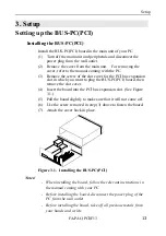
Page 18: ...in which you want to plug the BUS PC PCI board then remove the slot cover 4 Insert the board into the PCI bus expansion slot See Figure 3 1 5 Pull the board slightly to make sure that it will not come off 6 Use the screw removed in step 3 above to fasten the board 7 Attach the cover back in place Figure 3 1 Installing the BUS PC PCI Notes When installing the board follow the relevant instructions ...

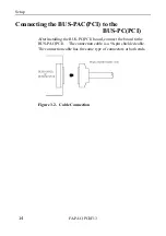
Page 19: ... PAC PCI to the BUS PC PCI After installing the BUS PC PCI board connect the board to the BUS PAC PCI The connection cable is a 96 pin shielded cable The connection cable has the same type of connectors at both ends Figure 3 2 Cable Connection ...

Page 20: ...on Turning off the system 1 Turn off the PC 2 The FA PAC PCI F13 enters the sleep mode in synchronization with the PC power supply 3 To power off the FA PAC PCI F13 completely turn off the main power supply disconnect the power plug from the wall outlet 1 You can manually turn on or suspend put to sleep the power supply of the FA PAC PCI F13 by pressing the POWER switch on the front panel Use this...

Page 21: ...using the FA PAC PCI F13 plug another BUS PC PCI board in an expansion slot in the PC main unit as illustrated below The bus cannot be expanded from any added expansion slot on the BUS PAC PCI Figure 3 3 Bus Expansion Using a Set of Three FA PAC PCI F13 Units ...

Page 22: ...n be rack mounted using the attached brackets The brackets can be used in two ways as illustrated below Rack mount the FA PAC PCI F13 using the brackets by the appropriate method suitable for the operating environment CONTEC CONTEC Figure 3 4 Attaching the Rack Mount Brackets ...

Page 23: ...Setup FA PAC PCI F13 18 ...

Page 24: ...e output current must not exceed the following values 5VDC 18A Max 3 3VDC 15A Max 12VDC 9A Max 12VDC 1A Max Total maximum output power 1 230W Input voltage 2 AC115 230V switch selectable Input frequency 50 60Hz Input current 6A AC 115V 4A AC 230V Operating conditions 0 50 C 20 80 not condensation allowed Storage conditions 0 60 C 10 90 not condensation allowed Outside dimensions 424mm W x 156mm H ...

Page 25: ...es of the parts may be extremely shortened if they are used where it is either exposed to must dirt metal chips or particles or dust or affected by oil or corrosive gas Power supply About 5 years in an office environment kept at a temperature of 25 C and a humidity of 60 Fan About 5 years in an office environment kept at a temperature of 25 C and a humidity of 60 Fan filter About 1 year in an offi...

Page 26: ...0 160 0 80 0 443 0 372 8 φ5 10 0 459 0 AIR OUT FAN Figure 4 1 Outside Dimensions of the FA PAC PCI F13 The parenthesized dimensions are measured with the rack mount brackets attached Notes When using this unit keep it at least 20mm away from any object such as the wall for cooling purposes Attaching rubber pads to the unit makes it 7mm taller ...

Page 27: ...0 90 not condensation allowed Outside dimensions 122 0 x 107 0 x 18 5 mm Weight 100g 1 If the PC is turned on in prior to the FA PAC PCI F13 no PCI board in the FA PAC PCI F13 is recognized 2 The current consumption assumes that only the PC is turned on without turning on the FA PAC PCI F13 3 Power is supplied from the PC main unit Item Specification 122 0 107 0 mm ...

Page 28: ...System Reference FA PAC PCI F13 23 System Block Diagram Figure 4 2 System Block Diagram Figure 4 3 Wiring Diagram ...

Page 29: ... B03 Ground A04 TDI 1 B04 TDO 1 A05 5V B05 5V A06 INTA O O B06 5V A07 INTC O O B07 INTB O O A08 5V B08 INTD O O A09 Reserved 1 B09 PRSNT1 2 Fixed to LOW A10 5V I O B10 Reserved 1 A11 Reserved 1 B11 PRSNT2 2 OPEN A12 Ground B12 Ground A13 Ground B13 Ground A14 Reserved 1 B14 Reserved 1 A15 RST I I B15 Ground A16 5V I O B16 CLK I I A17 GNT I B17 Ground A18 Ground B18 REQ O A19 Reserved 1 B19 5V I O ...

Page 30: ...3 I O I O B46 Ground A47 AD 11 I O I O B47 AD 12 I O I O A48 Ground B48 AD 10 I O I O A49 AD 09 I O I O B49 Ground A50 CONNECTOR 5 Volt Key B50 CONNECTOR 5 Volt Key A51 KEY 5 Volt Key B51 KEY 5 Volt Key A52 C BE 0 O I B52 AD 08 I O I O A53 3 3V B53 AD 07 I O I O A54 AD 06 I O I O B54 3 3V A55 AD 04 I O I O B55 AD 05 I O I O A56 Ground B56 AD 03 I O I O A57 AD 02 I O I O B57 Ground A58 AD 00 I O I ...

Page 31: ...nt consumption by the boards exceeds the power capacity of the FA PAC PCI F13 Check whether the cables connected to CN6 and CN7 on the PC MB14 PCI are the specified ones If the PCI board in the FA PAC PCI F13 won t be recognized Check whether the BUS PC PCI and BUS PAC PCI have been installed correctly Check whether the expansion bus cable has been connected correctly Check whether the FA PAC PCI ...

Page 32: ...ock Diagram 23 Bus Signals 24 C Connection 14 E Each Component 7 F Features 1 H Handling Precautions 3 I Introduction 1 L Liability 2 R Restrictions 4 Rack Mount Brackets 17 S Setup 13 Specifications 19 Starting up 15 T Troubleshooting 26 ...

Page 33: ...A 46 172 LZN7031 021018 000321 ...

Page 34: ...Kuro ku Seoul Korea Tel 82 2 2636 4277 8 Fax 82 2 2636 4279 E mail product conteck com CHINA INTERNATIONAL CONTEC TECHNOLOGY CO LTD B 8F Hua Tong Building No B19 Che Gong Zhuang West Road Hai Dian District Beijing 100044 China Tel 86 10 8801 8228 Fax 86 10 8801 8209 E mail ict ict com cn SHANGHAI CONTEC MICROELECTRONICS CORP No 481 Gui Ping Road Cao He Jing Hi Tech Park Shanghai 200233 China Tel 8...

Reviews: