6. About Hardware
66
AO-1616L-LPE, AO-1608L-LPE
Control Signal Timings
Control Signal Timings for Analog Output
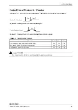
Figures 6.3, 6.4, 6.5, and Table 6.3 show the control signal timings for the analog output function.
Figure 6.3. Timing Chart of External Sampling Clock (Analog output)
Figure 6.4. Timing Chart of Sampling Start Control Signal
Figure 6.5. Timing Chart of Sampling Stop Control Signal
Table 6.3. Control Signal Timings
Parameter
Symbol Time
Unit
Delay from external sampling clock to actual start
t
DEC
100
nsec
Settling time
t
WS
10000
nsec
Set up time of sampling start (Rising edge)
t
SRS
100
nsec
Hold time of sampling start (Rising edge)
t
HRS
100
nsec
Set up time of sampling start (Falling edge)
t
SFS
100
nsec
Hold time of sampling start (Falling edge)
t
HFS
100
nsec
Set up time of sampling stop (Rising edge)
t
SRP
100
nsec
Hold time of sampling stop (Rising edge)
t
HRP
100
nsec
Set up time of sampling stop (Falling edge)
t
SFP
100
nsec
Hold time of sampling stop (Falling edge)
t
HFP
100
nsec
The times listed in Table 6.3 are for standard operating conditions.
External Smapling Clock Input
t
DEC
Conversion start
External Smapling Start Trigger Input
t
HRS
t
SRS
t
HFS
t
SFS
External Smapling Stop Trigger Input
t
HRP
t
SRP
t
HFP
t
SFP
CAUTION

