


2
CTUPO02_IG_en-GB_v1
PRIOR TO INSTALLATION
Read the manual prior to installation. Technical knowledge is necessary for installation. The place of installation
must be free of moisture and away from heat sources. Please ensure that the correct tools are used during the
installation to avoid damage to the vehicle or product. Connects2 can not be held responsible for the installation
of this product.
Note: The aftermarket stereo being installed must have female RCA connectors in order for this product to
function correctly
IN ISO CONNECTOR
Purple
Right Rear S
Purple/Black
Right Rear Speaker -
Green
Left Rear S
Green/Black
Left Rear Speaker -
Grey
Right Front S
Grey/Black
Right Front Speaker -
White
Left Front S
White/Black
Left Front Speaker -
ADDITIONAL CONNECTIONS
Pink
Speed
Pulse
Green
Park
Brake
Purple/White
Reverse Gear
Blue/White
Amp Remote
Grey
Mute
WIRING KEY
Yellow
Permanent 12V
Black
Ground
Red
Ignition 12V
Orange
Illumination
Red/White RCA (AUX)
AUX Input Retention
Red/White RCA (Speaker)
Amplifier/Audio Retention
Yellow RCA
Reversing Camera Retention
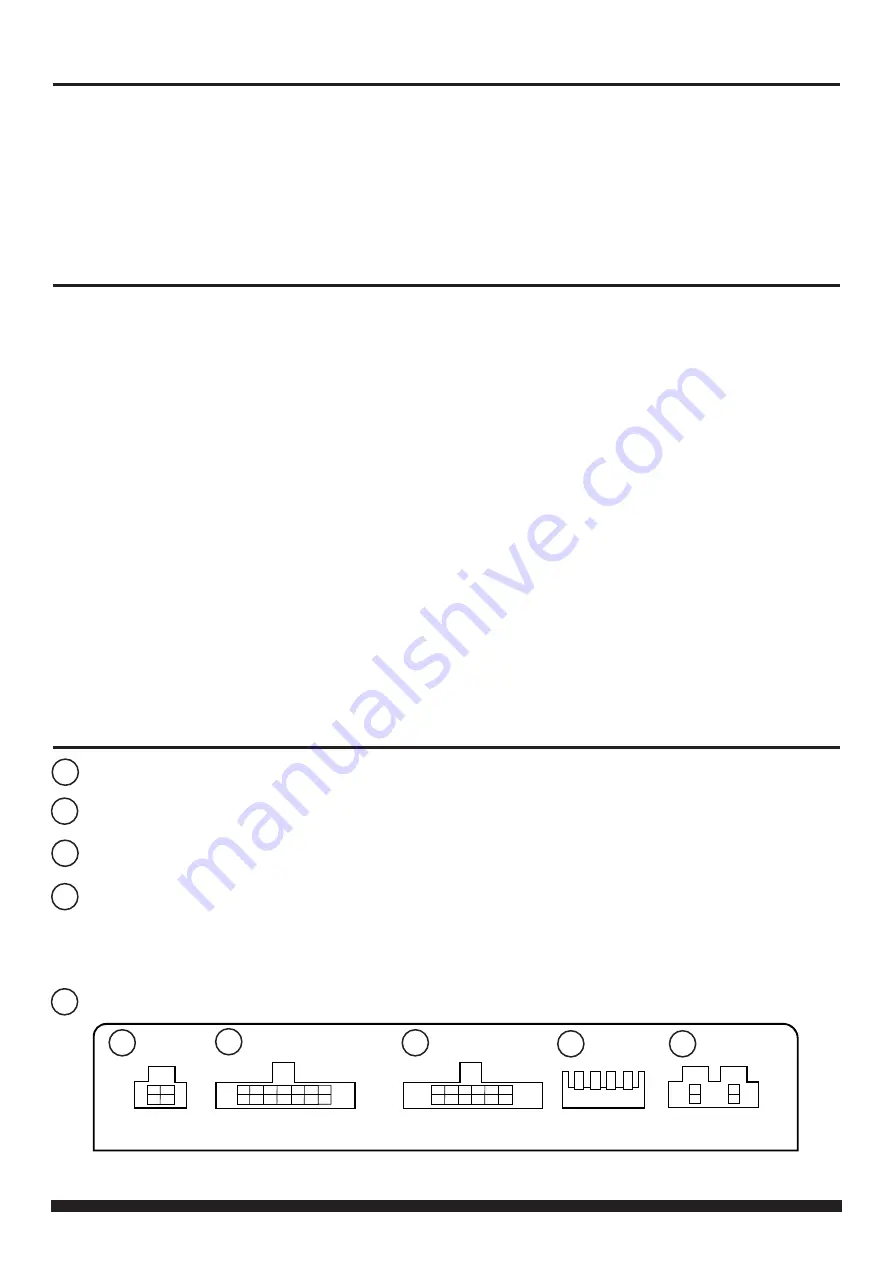
INTERFACE CONNECTIONS
1 2 3 4
DIP Switch 1 - ‘ON’ for Pioneer, ‘OFF’ for other brand head units
DIP Switch 1 - ‘ON’ for Pioneer, ‘OFF’ for other brand head units
DIP Switch 2 - ‘ON’ for PAL reversing camera, ‘OFF’ for NTSC reversing camera (Default is ‘OFF’/NTSC)
DIP Switch 2 - ‘ON’ for PAL reversing camera, ‘OFF’ for NTSC reversing camera (Default is ‘OFF’/NTSC)
DIP Switch 3 - Change from ‘OFF’ to ‘ON’ and back to reset screen settings to factory defaults.
DIP Switch 3 - Change from ‘OFF’ to ‘ON’ and back to reset screen settings to factory defaults.
Note: During this procedure, the screen background will change to red and no settings adjustments can be made.
Note: During this procedure, the screen background will change to red and no settings adjustments can be made.
DIP Switch 4 - Not Used
DIP Switch 4 - Not Used
1
2
3
4
5
1
4
2
3
5
Reverse Camera Extension Harness Input
Reverse Camera Extension Harness Input
Power Harness Input
Power Harness Input
Head Unit Connection (Patch) Lead Input
Head Unit Connection (Patch) Lead Input
Not used
Not used


