Connected IO Inc., CONFIDENTIAL
6
CIO Router: ER2500T-XX-CAT1 User Manual
Revision: 4.0
Number
Item
Description
4
WAN Port
WAN Port for establishing links to leased telecommunication circuits
LED: Solid Green for Link, Flashing Green for Traffic
5
LAN Port
LAN Port for Wired Ethernet Clients
LED: Solid Green for Link, Flashing Green for Traffic
Number
Item
Description
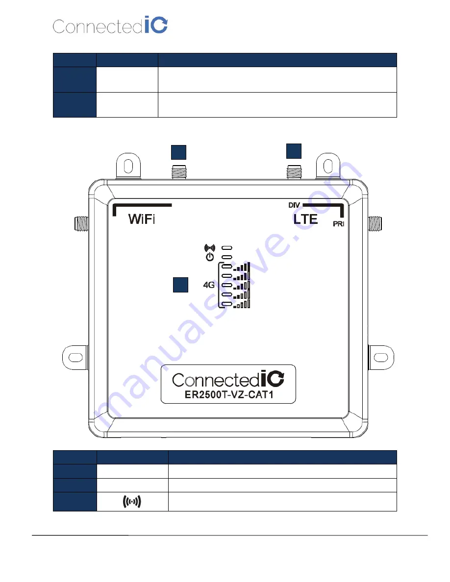
6
WiFi Antenna
SMA connector for WiFi Antennas (NOT Reverse Polarized)
7
Cellular Antennas
SMA connector for both Primary and Diversity Antenna Ports
8
WiFi LED, Orange: Wifi is connected/Off: No WiFi
6
7
8