


EN
25
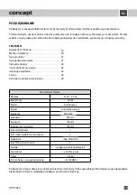
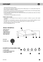
OPP2060
Operating Instructions
Before first use
Prior to the start of use of a new unit, wipe it with a wet and then a dry cloth.
Airing mode
In this mode the vapors are ventilated through the output pipe into the shaft and out of the room. If there are
carbon filters installed in the unit,
remove them
(see the Cleaning and Maintenance paragraph).
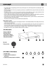
1. Select the required fan power (1 - 3) using the respective buttons (2)
2. Switch the unit off after use by pushing „0“.
Re-circulation mode
If you have no possibility to ventilate the air out of the room, re-circulation mode can be selected. In this mode the
vapors are filtered through metal and carbon filters. Active carbon in these filters absorbs smells, and the clean air
flows back to the room. For this mode it is necessary
to buy and assemble
the corresponding carbon filters (see
the Cleaning and Maintenance paragraph).
3. Select the required fan power (1 - 3) using the respective buttons (2)
4. Switch the unit off after use by pushing „0“.
Switching the lighting on and off
Press the button to turn the light on or off.
CLEANING AND MAINTENANCE
• Before any maintenance and cleaning, disconnect the power cord from the mains or switch off the circuit
breaker of the mains outlet of the unit.
•
Do not immerse the power cord, plug, or appliance in water or any other liquid.
• Set all controls in the OFF position.
• Clean the outer surface of the unit with a wet cloth, or use a neutral detergent.
• Do not use coarse sponges, abrasive cleaners, solvents or aggressive detergents.
• Do not use an autoclave to clean the unit!
CLEANING AND REPLACING THE FILTERS
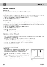
a) Metal fat filters
Under normal use, the metal fat filters should be cleaned every 2 months.
In case of more frequent frying or deep frying, shorten the interval.
Do not use the unit without properly mounted metal fat filters!
1. Remove the metal filters (Fig. 1). If carbon filters are mounted, remove
them.
2. Put the metal filters in warm water with a detergent. Clean them with
a soft brush, rinse with clean water and let dry.
3. Remount the completely dry filters following the reverse steps.
Fig. 1
EN
26
OPP2060
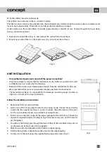
b) Carbon filters (must be purchased)
These filters are used only in the re-circulation mode.
The filters contain active carbon that absorbs the ventilated odors. After a while the active carbon is saturated, and
loses its absorption ability. These filters can‘t be washed or otherwise cleaned.
Under normal use, the carbon filters should be replaced every 2 months. In case of more frequent frying or deep
frying, shorten the interval.
1. Remove the metal filters (Fig. 1), and remove the carbon filters from them.
2. Mount new carbon filters on the metal ones (Fig. 2), and put the set back.
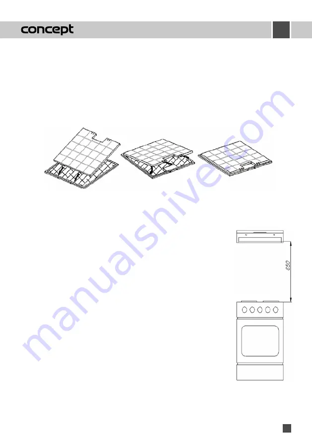
Fig. 2
UNIT INSTALLATION
• Only authorized personnel can install the power connection!
• Only the customer is responsible for installation in situ. Defects caused by incorrect
installation are not covered by the warranty.
• Remove all the covering and marketing materials from the unit before the first use.
• We recommend that you let a specialized company perform the installation.
• The manufacturer bears no responsibility for damage caused to people, animals or
objects as a result of incorrect installation.
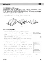
Follow the installation instructions:
1. Remove both fat (or carbon) filters.
2. Select one of the three output holes for the airing mode. Unused holes shall be
covered by the supplied casings so as not to reduce the performance of the unit.
For the re-circulation mode, close all the four output holes.
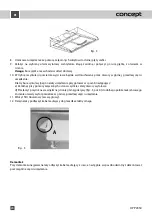
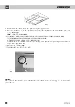
3. Put the unit on the lower edge of the upper cupboard of the kitchen set. Check the
minimum required height according to Fig. 3 (650 mm for electric, and 750 mm for
gas hotplates).
4. You will see the fixing holes through the lower orifice of the unit. Mark the positions
on the wall and bottom side of the cupboard.
5. Mark the position and diameter of the hole for output piping.
6. Drill the fixing holes in the wall, possibly also for the output piping.
7. Fix the unit to the wall using the supplied wall plugs and screws (Fig. 4).
Fig. 3
EN
31
OPP 2050
Summary of Contents for OPP 2050
Page 2: ......
Page 10: ......
Page 18: ......
Page 26: ......
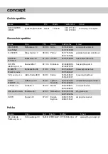
Page 34: ...CZ Seznam servisních míst SK Zoznam servisných stredisiek PL Wykaz punktów servisovych ...


