background image

IP HIGH SPEED DOME SERIES QUICK START GUIDE

4

CONFIGURING THE CAMERA

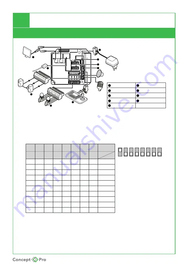
Camera Connections

3

Alarm Input Terminal Block

1

BNC 1 CVBS Output

2

Network Connection

4

Alarm Output Terminal Block

5

6

DC 12V/ AC 24V Power Input

RS-485 Connector

Camera Setting Set Switch

8

Address ID Set Switch

7

9

DC12V Output

Cabling

BNC1

1

2

3

4

Speaker 

Mic.

ALARM INPUT

GND

1

2

3

4

5

6

7

8

COM

In 1

In 8

OUT1

OUT2

OUT3

OUT4

5

6

8

7

9

BNC2

1.  VIDEO OUTPUT 

BNC1: 

Analogue


(CVBS) Output.  

2.  Address ID Switch 


1

2

3

4

5

6

7

8

ON

ON

OFF

ON

ON

ON

ON

OFF

OFF

OFF

---

OFF

ON
ON

OFF

ON

ON

OFF

ON

OFF

---

OFF
OFF
OFF

ON

ON

ON

ON

ON

OFF

---

OFF
OFF
OFF

OFF

OFF

ON

OFF

OFF

ON

---

OFF
OFF
OFF

OFF

OFF

ON

OFF

OFF

OFF

---

OFF
OFF
OFF

OFF

OFF

ON

OFF

OFF

OFF

---

OFF
OFF
OFF

OFF

OFF

ON

OFF

OFF

OFF

---

OFF
OFF
OFF

OFF

OFF

ON

OFF

OFF

OFF

1

---

2
3

5

7

4

255

6

8

-

1

1

2

3

4

5

6

7

8

2

DIP

4

8 16 32 64 128 Val ID

Factory default

switch positions

Speed dome ID is set using 

standard binary notation

1

2

4

8

16

32

65 128


Note: ID 0 should not be used. Where multiple speed domes  

are connected, a unique ID must be assigned to each one.


Summary of Contents for CP-HSD20-IP

Page 1: ...IP HIGH SPEED DOME SERIES QUICK START GUIDE CP HSD20 30 IP IP PTZ QUICK START GUIDE ...

Page 2: ...eet to drill holes in the mounting surface then affix the included bracket to the surface 2 Connect the safety lanyard between the camera and bracket then connect all required cables to the camera 3 Twist the camera into the bracket and tighten the fixing screws 3 WALL MOUNT INSTALLATION 1 Drill holes and affix wall bracket to surface and pass cable through to junction box 2 Configure DIP switches...

Page 3: ...IDEO OUTPUT BNC1 Analogue CVBS Output 2 Address ID Switch 1 2 3 4 5 6 7 8 ON ON OFF ON ON ON ON OFF OFF OFF OFF ON ON OFF ON ON OFF ON OFF OFF OFF OFF ON ON ON ON ON OFF OFF OFF OFF OFF OFF ON OFF OFF ON OFF OFF OFF OFF OFF ON OFF OFF OFF OFF OFF OFF OFF OFF ON OFF OFF OFF OFF OFF OFF OFF OFF ON OFF OFF OFF OFF OFF OFF OFF OFF ON OFF OFF OFF 1 2 3 5 7 4 255 6 8 1 1 2 3 4 5 6 7 8 2 DIP 4 8 16 32 64...

Page 4: ...15 16 for additional details Note If the plug in could not be successfully installed one possibility is that the operating system and the browser are not compatible For example if the operation system is 64 bits but the browser is 32 bits then the 32 bit plug in will need to be installed 4 CONFIGURING THE CAMERA Camera Connections 3 SET SWITCHES DIP No 1 and 2 configures the baud rate as follows 1...

Page 5: ... for configuring image qual ity settings and any other settings within the camera options While the IP camera supports RS485 with access to the OSD menu via preset 95 when editing the camera from the OSD menu the settings may not change therefore synchronisation is not possible using the web browser However when changes are made from the web browser these are synchronised to the OSD menu I IP PCam...

Page 6: ...ow to connect and operate the camera via IE 5 Input Output This product supports audio in out analogue CVBS output and up to 64GB Micro SD card Audio in GND Audio out Speaker Mic 6 Power Supply Only use recommended power supply adapters with this camera AC24V DC12V PoE Optional ...

Page 7: ...IP HIGH SPEED DOME SERIES QUICK START GUIDE NOTES ...

Page 8: ...IP HIGH SPEED DOME SERIES QUICK START GUIDE ...

Reviews: