ES8105-GigE
Introduction
The RocketLinx ES8105-GigE and ES8108-GigE are industrial Ethernet switches with full
Gigabit ports that are backward compatible (10/100/1000BASE-TX). The ES8105-GigE has
five Gigabit ports and the ES8108-GigE has eight Gigabit ports. The ES8105-GigE and
ES8108-GigE are referred to as the switch in the remainder of the Guide unless
model-specific information is required.
The switches conform to IEEE802.1p Class of Service, IEEE802.1Q Quality of Service for
packet forwarding precedence, and IEEE802.3x Flow Control standards. The switches
provide 9.6K bytes Jumbo frame (Gigabit) for large file transmission and supports broadcast
storm packet filtering.
The switches feature a compact IP31 rigid aluminum case for operation in harsh
environments (-10°C to 70 C). They also feature an alarm relay to notify users of a port link or
power failure. The switches can be powered using a wide input power range of 12-48VDC
using the 6-pin terminal block.
Setting the DIP switch
The RocketLinx switches have a DIP switch located on the bottom panel to configure the port
link or power failure alarm.
1
2
3
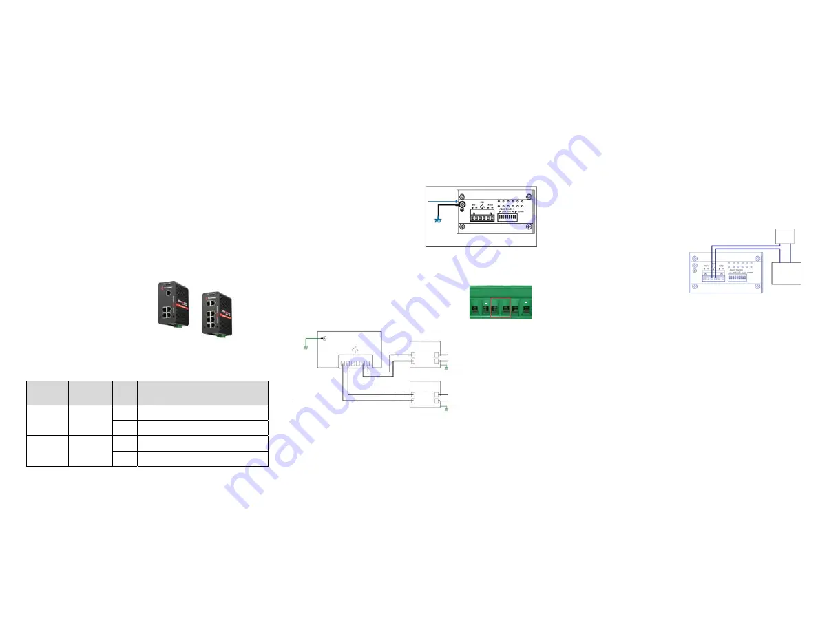
Grounding the Switch
There is an earth ground screw on the bottom
side of the switch. Connect the earth ground
screw of the switch to a grounding surface to
ensure safety and prevent noise.
It is not necessary to attach a ground wire if
the DIN rail is grounded and the switch is
mounted on the DIN rail.
Wiring the Power
Use the following procedure to wire the power. The switches allow redundant DC power input.
Note: The recommended working voltage is 24VDC (12-48VDC).
1. Disconnect the terminal block from the switch.
2. Insert the positive and negative wires into the + and - contact
either under the PW1 and/or PW2 on the terminal block
connector.
Note: Power should be disconnected from the power supply before connecting it to the switch.
Otherwise, your screwdriver blade can inadvertently short your terminal connections to the
grounded enclosure.
3. Tighten the wire-clamp screws to prevent the wires from being loosened.
4. Plug the terminal block into the switch.
PW1
Alarm
PW2
+
+
On
ES8105-GigE
ES8108-GigE
Status
Description
DIP 1 to DIP 5
DIP 1 to DIP 8
DIP 6
DIP 9
Enables the port link down alarm on the corresponding port.
Disables the port link down alarm on the corresponding port.
Enables the power failure alarm.
Disables the power failure alarm.
Off
On
Off
Wiring the Alarm Relay
The alarm relay contacts are in the middle of the terminal block connector. By inserting the
wires and setting the DIP switch of the respective Port Alarm to ON, the alarm relay detects
any port failures and forms a short circuit. The alarm relay is normally open. It closes if there is
a port or power failure.
The following graphic illustrates the ES8108-GigE, which has a DIP switch with 9 switches.
1. Insert the positive and negative wires as shown
in the graphic.
2. Tighten the wire-clamp screws to prevent the
wires from coming loose.
Mounting the Switch
The DIN rail clip is already attached on the rear
of the switch.
1. Insert the upper end of the DIN rail clip into the back of the DIN rail track from its
upper side.
2. Lightly push the bottom of the DIN rail clip into the track.
3. Verify that the DIN rail clip is tightly attached to the track.
Connecting the Ethernet Ports
You can use the following information to connect standard Ethernet cables between the
Ethernet ports and the network nodes. The Ethernet ports support 10BASE-T, 100BASE-TX,
and 1000BASE-TX, full-or half-duplex modes.
All ports automatically detect the signal from the connected devices to negotiate the link speed
and duplex mode (half- or full-duplex). Auto MDI/MDIX allows you to connect another switch,
hub, or workstation without changing straight-through or crossover cables. Crossover cables
cross-connect the transmit lines at each end to the received lines at the opposite end.
Extra Power
System
Maximum current 1A/24VDC
Alarm System
Power Supply
12-40VDC/1A
AC Power Input
Line
Neutral
Earth Ground
AC Power Input
Line
Neutral
Earth Ground
Power Supply
12-48VDC/1A
V-
V+
V-
V+
12-48VDC
DC Power Output
12-24AWG Wire
12-24AWG Wire
Bottom Side
12-48VDC
DC Power Output
Alarm
PWR1
PWR2
V+ V-
V+ V-
Earth Ground
Screw
Earth Ground
Warning: Do not connect to AC line - Neutral
ES8108-GigE


