background image

6.4.3 Parental 

Control 

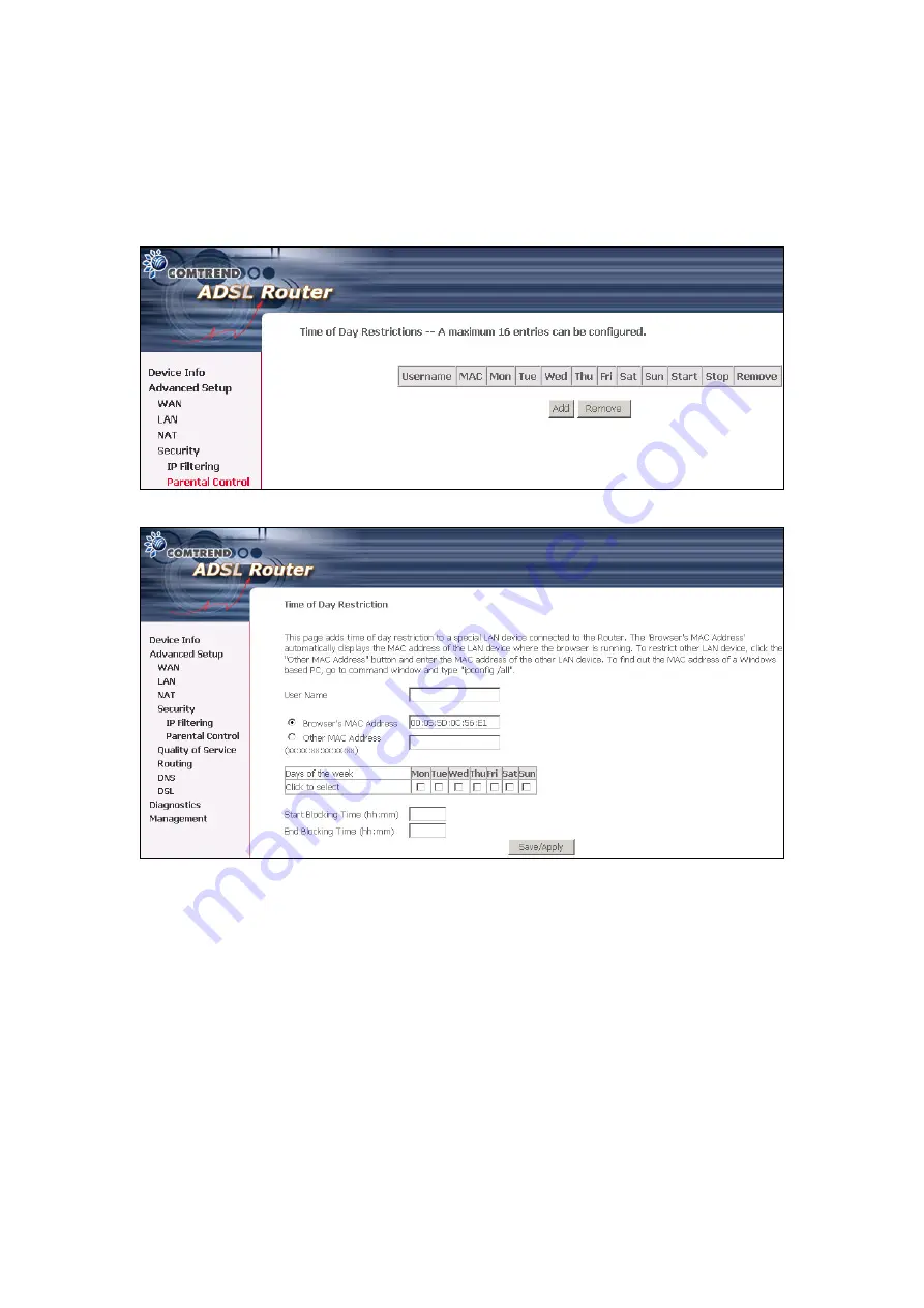
This feature restricts access from a LAN device to an outside network through the 
device on selected days at certain times.  Make sure to activate the Internet Time 
server synchronization as described in section

 8.3 Internet Time

, so that the 

scheduled times match your local time. 


Click 

Add 

to display the following screen. 


See below for instructions.  Click 

Save/Apply

 to apply the settings.   


User Name:

 A user-defined label for this restriction. 


Browser's MAC Address:

 MAC address of the PC running the browser. 


Other MAC Address:

 MAC address of another LAN device.  


Days of the Week:

 The days the restrictions apply. 


Start Blocking Time:

 The time the restrictions start. 


End Blocking Time:

 The time the restrictions end. 


56

Summary of Contents for CT-5611E

Page 1: ...CT 5611E ADSL2 Combo Router for Annex B User Manual Version A1 0 June 2 2008 261070 009...

Page 2: ...evision or software upgrades visit our website at http www comtrend com Warning Before servicing disconnect power and telephone lines from the device Use an appropriate power supply and a UL Listed te...

Page 3: ...31 4 2 4 Bridging 33 CHAPTER 5 DEVICE INFORMATION 35 5 1 WAN 36 5 2 STATISTICS 37 5 2 1 LAN Statistics 37 5 2 2 WAN Statistics 37 5 2 3 ATM statistics 38 5 2 4 ADSL Statistics 39 5 3 ROUTE 42 5 4 ARP...

Page 4: ...ERNET TIME 70 8 4 ACCESS CONTROL 71 8 4 1 Services 71 8 4 2 IP Addresses 71 8 4 3 Passwords 72 8 5 UPDATE SOFTWARE 73 8 6 SAVE AND REBOOT 74 APPENDIX A PIN ASSIGNMENTS 75 APPENDIX B SPECIFICATIONS 76...

Page 5: ...protocol and supports advanced security functions 1 1 Features Annex B IP filtering SPI Stateful Packet Inspection DoS protection Static route Dynamic IP assignment NAT PAT IGMP Proxy DHCP Server Rela...

Page 6: ...established ADSL LINK Green Blink The ADSL link is training On A USB link is established Off A USB link is not established USB Green Blink Data transmitting or receiving over USB On The ADSL TR RX lin...

Page 7: ...ort Attach the power adapter to a wall outlet or other AC source Press the power button to the ON position IN If the Power LED indicator lights up GREEN then the device is ready for setup Caution 1 If...

Page 8: ...n supports Win ME Win 98 Win 2000 Win XP 32 bit and Vista 32 bit For those using Windows XP 64 bit the driver must be installed manually please see section 2 3 below for details Follow the procedure b...

Page 9: ...llowing window will be displayed Click the Next button to continue STEP 3 When the window displays as below wait for the drivers to fully install STEP 4 Click the Finish button when the window display...

Page 10: ...STEP 5 The installation is complete You can now connect the device to your PC using a standard USB cable 9...

Page 11: ...edure below to manually install the 64bit USB driver STEP 1 Connect the USB port to the PC by plugging the flat connector of a standard USB cable into your PC and plugging the square connector into th...

Page 12: ...he Next button NOTE This window won t display if the USB Driver has been previously installed In this case contact technical support for assistance STEP 3 Insert the installation CD NOTE If you see th...

Page 13: ...f the file using the Browse button as shown above Normally the file is on the CD ROM shipped with the device STEP 5 Locate the Vista folder and click OK STEP 6 When the window displays as below click...

Page 14: ...13...

Page 15: ...STEP 7 Click the Finish button when the window displays as below STEP 8 Installation is complete 14...

Page 16: ...ng Technical Note During power on the device initializes all settings to default values It will then read the configuration profile from the permanent storage section of flash memory The default attri...

Page 17: ...the steps below to configure your PC IP address to use subnet 192 168 1 x The following assumes you are running Windows XP STEP 1 From the Network Connections window open Local Area Connection You ma...

Page 18: ...s STEP 1 Start the Internet browser and enter the default IP address for the device in the Web address field For example if the default IP address is 192 168 1 1 type http 192 168 1 1 NOTE For local a...

Page 19: ...or the first time you will reach this screen NOTE1 If a PVC connection already exists then this Quick Setup screen will be bypassed and the Device Info Summary screen will display instead NOTE2 The se...

Page 20: ...er is to run the PPPoE client The router can support both cases simultaneously If some or none of the LAN side devices do not run PPPoE client then select PPPoE If every LAN side device is running a P...

Page 21: ...to display the DSL Quick Setup screen STEP 2 Click Next to start the setup process Follow the onscreen prompts STEP 3 After setup is complete the device will reboot NOTE After the device reboots the D...

Page 22: ...u and uncheck the DSL Auto connect checkbox to begin the manual quick setup process Uncheck to begin the manual quick setup process and display the following screen STEP 2 Adjust the VPI VCI settings...

Page 23: ...function is not available for this router Click Next to continue NOTE The subsections that follow continue the ATM PVC setup procedure Enter the appropriate settings for your service Choosing differe...

Page 24: ...some service providers Unless your service provider specifically requires this setup do not select it PPP IP Extension does the following Allows only one PC on the LAN The public IP address assigned b...

Page 25: ...nd PPPoA The default values are 1492 for PPPoE and 1500 for PPPoA STEP 5 This screen allows the user to control IGMP Multicast and WAN Service Enable IGMP Multicast checkbox Tick the checkbox to enabl...

Page 26: ...nd enter starting and ending IP addresses and the leased time This setting configures the router to automatically assign IP default gateway and DNS server addresses to every PC on your LAN Please be a...

Page 27: ...ettings STEP 8 Click Save Reboot to apply these settings The configuration will be saved to flash memory and then the device will reboot After the device reboots the Web UI should refresh the browser...

Page 28: ...in MER mode when Obtain an IP address automatically is chosen Changing the default gateway or the DNS affects the whole system Configuring them with static values will disable the automatic assignmen...

Page 29: ...wall If the firewall checkbox is selected the Security submenu will display after the next reboot The user can then configure firewall features If the firewall is not used this checkbox should not be...

Page 30: ...gn IP default gateway and DNS server addresses to every PC on your LAN Please be aware that the private address range e g 192 168 1 2 192 168 1 254 can never include the router s LAN interface IP addr...

Page 31: ...ettings STEP 8 Click Save Reboot to apply these settings The configuration will be saved to flash memory and then the device will reboot After the device reboots the Web UI should refresh the browser...

Page 32: ...with a private IP address the user should select this checkbox The NAT submenu will display after the next reboot The user can then configure NAT related features If a private IP address is not used o...

Page 33: ...r To enable DHCP select Enable DHCP server and enter starting and ending IP addresses and the leased time This setting configures the router to automatically assign IP default gateway and DNS server a...

Page 34: ...n will be saved to flash memory and then the device will reboot After the device reboots the Web UI should refresh the browser window If the browser does not refresh restart the browser and login agai...

Page 35: ...cannot be accessed remotely in this mode STEP 6 Click Next to display the WAN Setup Summary screen that presents the entire configuration summary Click Back to modify the settings STEP 7 Click Save Re...

Page 36: ...i e local or remote For example in the Advanced Setup menu if NAT and Firewall are enabled the main menu will display the NAT and Security submenus If either is disabled their corresponding menu s wi...

Page 37: ...vice classes Service Shows the name for WAN connection Interface Shows connection interfaces Protocol Shows the connection type such as PPPoE PPPoA etc IGMP Shows the status of the IGMP Proxy function...

Page 38: ...een shows statistics for the Ethernet interface on the LAN Interface Shows connection interfaces Received Transmitted Bytes Pkts Errs Drops Rx TX receive transmit packet in bytes Rx TX receive transmi...

Page 39: ...rrors Number of cells dropped due to uncorrectable HEC errors In Unknown Number of received cells discarded during cell header validation including cells with unrecognized VPI VCI values and cells wit...

Page 40: ...ut Discards This field is not currently used ATM AAL5 LAYER STATISTICS FOR EACH VCC OVER ADSL INTERFACE Field Descriptions VPI VCI ATM Virtual Path Channel Identifiers CRC Errors Number of PDUs receiv...

Page 41: ...40...

Page 42: ...er of Mux Data Frames in FEC Data Frame T Max Data Frames over sync bytes R Number of check bytes in FEC Data Frame S Ratio of FEC over PMD Data Frame length L Number of bits in PMD Data Frame D The i...

Page 43: ...he ADSL BER Test button A small window will open when the button is pressed it will appear as shown below Click Start to start the test or Close If the test is successful the pop up window will displa...

Page 44: ...use gateway H target is a host R reinstate route for dynamic routing D dynamically installed by daemon or redirect M modified from routing daemon or redirect Metric The distance to the target usually...

Page 45: ...to display the ARP information Field Description IP address Shows IP address of host pc Flags Complete Incomplete Permanent Publish HW Address Shows the MAC address of host pc Device Shows the connec...

Page 46: ...ases Field Description Hostname Shows the device host PC network name MAC Address Shows the Ethernet MAC address of the device host PC IP address Shows IP address of device host PC Expires In Shows ho...

Page 47: ...utton under the Remove column of the table and click the Remove button under the table Heading Information VPI VCI ATM VPI 0 255 VCI 32 65535 Con ID WAN connection ID number Category ATM service categ...

Page 48: ...N This screen allows the user to configure the LAN Interface on the device It is similar to the DEVICE SETUP screen in Quick Setup but with more options NOTE NAT is disabled above so UPnP is hidden se...

Page 49: ...nd enter DHCP Server IP address This allows the Router to relay the DHCP packets to the remote DHCP server The remote DHCP server will provide the IP address This option is hidden if NAT is enabled Co...

Page 50: ...private IP addresses on the LAN side The Internal port is required only if the external port needs to be converted to a different port number used by the server on the LAN side A maximum of 32 entries...

Page 51: ...elected the port ranges are automatically configured Internal Port End Enter the internal port ending number when you select Custom Server When a service is selected the port ranges are automatically...

Page 52: ...ed the port ranges are automatically configured Trigger Protocol TCP TCP UDP or UDP Open Port Start Enter the starting open port number when you select custom application When an application is select...

Page 53: ...A and MER use IP Filtering pg 54 to perform a similar function Each network device has a unique 48 bit MAC address This can be used to filter block or forward packets based on the originating device M...

Page 54: ...Save Apply to save and activate the filter rule Field Description Protocol Type PPPoE IPv4 IPv6 AppleTalk IPX NetBEUI IGMP Destination MAC Address Defines the destination MAC address Source MAC Addre...

Page 55: ...s ACCEPTED Under this condition all outgoing IP packets that match the filter rules will be BLOCKED To add a filtering rule click the Add button The following screen will display Filter Name Type a na...

Page 56: ...d button The following screen will display For detailed field descriptions please reference the Outgoing IP Filter table Under WAN Interfaces select the PVCs routing mode with firewall only where the...

Page 57: ...cheduled times match your local time Click Add to display the following screen See below for instructions Click Save Apply to apply the settings User Name A user defined label for this restriction Bro...

Page 58: ...rvice NOTE QoS must be enabled in at least one PVC to display this option see Advanced Setup WAN for detailed PVC setup instructions Click Add to configure network traffic classes The following screen...

Page 59: ...e number the higher the priority SET 1 Physical LAN Port Select between ENET and USB Protocol TCP TCP UDP UDP or ICMP Source IP Address Enter the source IP address Source Subnet Mask Enter the subnet...

Page 60: ...t the first received default gateway assignment from one of the enabled PVC s If the checkbox is not selected enter the static default gateway and or WAN interface Click Save Apply button to save it N...

Page 61: ...dd the entry to the routing table 6 7 DNS 6 7 1 DNS Server If the Enable Automatic Assigned DNS checkbox is selected this device will accept the first received DNS assignment from one of the DHCP enab...

Page 62: ...uration effective 6 7 2 Dynamic DNS The Dynamic DNS service allows a dynamic IP address to be aliased to a static hostname in any of many domains allowing the CT 5611E to be more easily accessed from...

Page 63: ...S provider from the list Hostname Enter the name for the dynamic DNS server Interface Select the interface from the list Username Enter the username for the dynamic DNS server Password Enter the passw...

Page 64: ...t s Upstream 0 5 Mbit s T1 413 Downstream 8 Mbit s Upstream 1 0 Mbit s ADSL2 Downstream 12 Mbit s Upstream 1 0 Mbit s AnnexL Supports longer loops but with reduced transmission rates ADSL2 Downstream...

Page 65: ...Indicates that the Ethernet interface on your computer is connected to the LAN port of the router Fail Indicates that the router does not detect the Ethernet interface on your computer USB connection...

Page 66: ...ty Therefore if this test fails but you are still able to access the Internet there is no need to troubleshoot this issue Ping Primary Domain Name Server Pass Indicates that the router can communicate...

Page 67: ...m the Settings submenu to access the screen shown below Click the Backup Settings button to save the current configuration settings You will be prompted to define the location of a backup file to save...

Page 68: ...the browser window and reopen If necessary reconfigure your PC IP address to match your new configuration see section 3 2 IP Configuration for details After a successful reboot the browser will retur...

Page 69: ...system events and configuration of related options The default setting for the System Log is enabled Follow the steps below to enable and view the System Log STEP 1 Click Configure System Log to begi...

Page 70: ...ion Informational provides information for reference Debugging debug level messages Emergency is the most serious event level whereas Debugging is the least important For instance if the log level is...

Page 71: ...wn below First NTP timeserver Select the required server Second NTP timeserver Select second timeserver if required Time zone offset Select the local time zone Configure these options and then click S...

Page 72: ...will be displayed if the WAN interface is down 8 4 1 Services The Services option limits or opens the access services over the LAN or WAN These access services are available FTP HTTP ICMP TELNET and...

Page 73: ...to the following three user accounts root is to be used for local unrestricted access control support is to be used for remote maintenance of the device user is to be used to view information and upda...

Page 74: ...ame field or click the Browse button to locate the image file Step 3 Click the Update Software button once to upload and install the file NOTE 1 The update process will take about 2 minutes to complet...

Page 75: ...CP server is disabled Static IP settings must be configured See section 3 2 IP Configuration for detailed instructions NOTE2 If you lose all access to the web user interface WUI you may need to close...

Page 76: ...ssignments Line Port RJ11 Pin Definition Pin Definition 1 4 ADSL_TIP 2 5 3 ADSL_RING 6 LAN Port RJ45 Pin Definition Pin Definition 1 Transmit data 5 NC 2 Transmit data 6 Receive data 3 Receive data 7...

Page 77: ...te RFC 2516 PPPoE RFC 1577 IPoA VCs 8 AAL AAL5 ATM service class UBR CBR VBR ATM UNI support UNI3 1 4 0 OAM F4 F5 Yes Management SNMP Telnet Web based management Configuration backup and restoration S...

Page 78: ...vironmental Tolerance Operating temperature 0 50 degrees Celsius Relative humidity 5 90 non condensing Dimensions 92 mm W x 34 mm H x 114 mm D Certifications FCC Part 15 class B FCC Part 68 NOTE Speci...

Page 79: ...g from the LAN can be dropped Filter Name User defined Filter Name Protocol Can take on any values from TCP UDP TCP UDP or ICMP Source IP Address Source Subnet Mask Packets with the particular Source...

Page 80: ...cepted Source Port This can take on either a single port number or a range of port numbers Packets having a source port equal to this value or falling within the range of port numbers portX portY will...

Page 81: ...o Drop all MAC layer frames except those explicitly stated in the rules Protocol Type Either PPPoE IPv4 IPv6 AppleTalk IPX NetBEUI IGMP Destination MAC Address Of the form XX XX XX XX XX XX Frames wit...

Page 82: ...isplays MAC address of the LAN device on which the browser is running Other MAC Address If restrictions are to be applied to a device other than the one on which the browser is running the MAC address...

Reviews: