background image

15

Repeat the steps for the top modem. Note that the circular and rectangular holes are opposite of the 
bottom modem. 

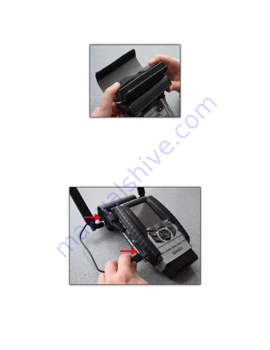
AntennAs And usb CAbles

Attach the antennas to each modem and insert the micro-USB connectors with the provided USB to 
micro-USB cables.

Insert the USB connectors into the top and side USB ports on the ACCESS 2USB. 

Summary of Contents for connect

Page 1: ...Product Manual Comrex Connect Modems for ACCESS ...

Page 2: ...tworks worldwide Connect modems for Verizon do not support 3G services Verizon version The Comrex Connect for Verizon is able to work on the network s main LTE channel at 700MHz known as Band 13 In addition it can operate on the AWS Band 4 marketed as XLTE by Verizon AT T version The Comrex Connect for AT T is able to work on the following LTE bands 700MHz Band 17 850Mhz Band 5 AWS Band 4 1900 MHz...

Page 3: ...00MHz BAND 3 2100 1700MHz BAND 4 850MHz BAND 5 2600MHz BAND 7 900MHz BAND 8 700MHz a BAND 12 700MHz c BAND 13 800MHz BAND 20 1900MHz BAND 25 850MHz BAND 26 700MHz BAND 29 2300MHz BAND 30 2500MHz TDD BAND 41 And covers the following 3G bands 2100MHz BAND 1 1900MHz BAND 2 1800MHz BAND 3 2100 1700MHz BAND 4 850MHz BAND 5 900MHz BAND 8 ...

Page 4: ... common exclusive of China Japan and India Most Chinese carriers use TDD so support is limited to carriers that operate on Band 41 In Japan support is limited to carriers operating on bands 8 1 and 3 In India some carriers use band 41 TDD and others use Band 3 In Oceania and the Middle East Bands 7 and 3 are common In Canada Latin America and the Caribbean Bands 7 and 4 are common Arranging LTE Se...

Page 5: ...he Connect Modem Chassis The Comrex Connect modem has a captive thumbscrew that can be turned to open the chassis Once the thumbscrew is completely loose pull down on the top cover toward the USB jack to remove it ...

Page 6: ... use a full size SIM card Smaller sizes can be accommodated with the included SIM adapters For the AT T and Verizon models the SIM card is inserted as shown below If using an adapter first insert the SIM into the adapter as completely as possible then apply the entire assembly to the SIM socket ...

Page 7: ...Once the SIM is installed correctly reattach the modem s top cover and re secure the thumbscrew Antenna The external antenna is required for proper modem operation The antenna is designed to work over all the LTE and 3G bands supported by the modem Attach the antenna to the SMA jack securely as shown below ...

Page 8: ...CESS Portable chassis To attach the pouch remove the top two Philips screws that secure the handstrap slot on the back of the ACCESS Place the pouch assembly so that the mounting screws align with these holes and apply the provided mounting screws through both the pouch assembly and the handstrap slot assembly ...

Page 9: ...in the pouch so that the SMA jack is lined up with the circular hole on the pouch and the micro USB connector is aligned with the rectangular hole on the pouch Fold the side flaps over the top of the modem on both sides ...

Page 10: ...ck side of the ACCESS Portable so that the velcro is facing out along the back of the modem Fold the longer flap with the Comrex logo over the modem and attach to the smaller velcro flap The pouch should now be snug and securely closed ...

Page 11: ...10 Attach the antenna to the SMA jack securely Connect the USB cable by seating the micro USB into the micro USB connector on the modem ...

Page 12: ...he side USB connector on ACCESS ACCESS Connect Modems EXT If you have purchased the EXT modem to use along with another Connect modem you will need to attach the EXT model first and then the standard pouch model The image below shows the two modems in pouches with antennas attached ...

Page 13: ...the four Philips screws that secure the handstrap slot on the back of the ACCESS With the handstrap slot still attached and screws removed take the EXT modem and align the 4 holes on the back plate to the four screw holes ...

Page 14: ...y the two silver screws provided with the EXT modem into the two bottom holes Align your standard Connect Modem bracket to the two top holes of the EXT bracket Apply the two black screws with washers provided ...

Page 15: ...o the pouch simply slide the modem with the antenna facing the circular hole and the USB connector facing the rectangular hole Fold up the flaps on each side under the top pouch Fold the bottom flap up Fold the top flap down and over the bottom flap s velcro ...

Page 16: ...d rectangular holes are opposite of the bottom modem Antennas and usb cables Attach the antennas to each modem and insert the micro USB connectors with the provided USB to micro USB cables Insert the USB connectors into the top and side USB ports on the ACCESS 2USB ...

Page 17: ...he following AT T Verizon International See the ACCESS user manual for more info on configuring APNs for modems INDICATORS The Connect modem has two LED indicators The red LED indicates power is active to the modem The green LED has different behavior depending on the type of modem Verizon Flashing green indicates the modem is registered with the network International Solid green indicates the mod...

Reviews: