Compuprint 6314/6414 - User Manual
4
7
12
3
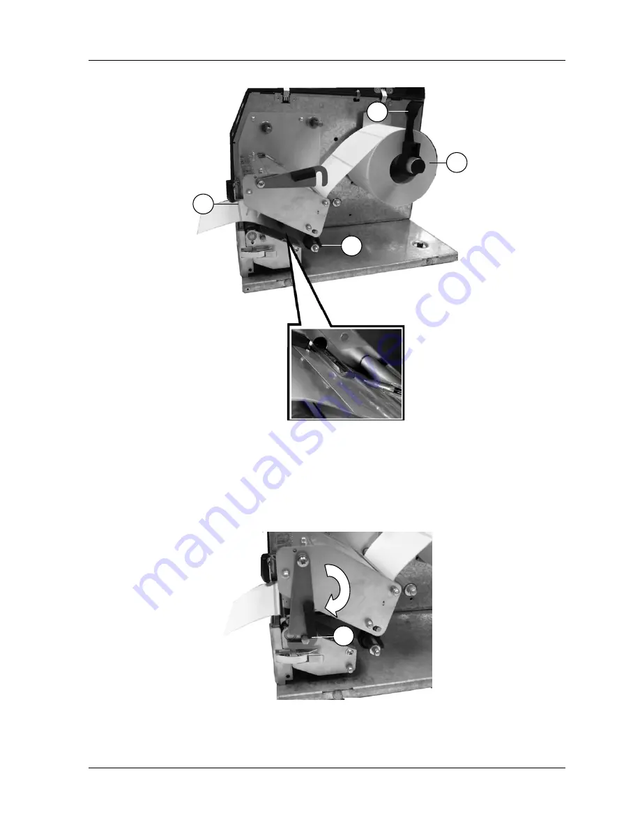
Fig. 12 – Label roll insertion and detail of paper path/sensor
-
Move the print head lock lever (11) to the closed position (13) (see Fig. 13).
11
Fig. 13 – Closing the print head assembly
21
Page 1: ...Compuprint 6314 6414 User Manual rel 002...
Page 2: ...only at its base Do not raise the printer holding it at the side grip because the printer cover may open the printer fall harming the user and or damaging the printer itself Sferal wwt srl Via Martiri...
Page 3: ...ading Media And Ribbon _________________________________________________________ 18 2 2 1 Loading Labels Inside The Printer___________________________________________________________19 2 2 2 Loading L...
Page 4: ..._______________________ 53 3 5 14 Set Time And Date _____________________________________________________________________ 53 3 5 15 Override Print Parameters __________________________________________...
Page 5: ...__________________________________________________68 3 12 6 Workgroup Name_______________________________________________________________________68 3 12 7 Enabling SMTP _______________________________...
Page 6: ...y with all information highlighted under special headings WARNING Conditions that could harm you as well as damage the equipment IMPORTANT Information vital to proper operation of the printer NOTE Inf...
Page 7: ...s one at a time before printing the next label Tear Off mode for positioning the label at the tear off position and detecting its removal before printing the next label Tear Off Strip mode for printin...
Page 8: ...cts with the ribbon and bonds the image to the paper This method is used especially for abrasive long storage applications and for specialized applications such as in extreme environmental conditions...
Page 9: ...can enhance the versatility of your printer Fonts A selection of fonts is available to extend the capabilities of the standard resident fonts Media Cutter The cutter is used to automatically cut prin...
Page 10: ...al connectors to prevent electrostatic discharge damage while setting up the printer WARNING The discharge of electrostatic energy that accumulates on the surface of the human body or other surfaces c...
Page 11: ...rmal printer kit contains the items listed below The thermal printer AC Power cord User s Manual Quick Reference Manual Software Starter Kit CD Ribbon Take Up Core mounted in printer NOTE If any items...
Page 12: ...2 ON OFF Power Switch Attach Interface Fig 3 A Parallel Interface Attach a suitable parallel printer cable from the computer to the Centronics interface connector at the back of the printer Snap the...
Page 13: ...ection of all available interfaces using the AUTOMATIC feature The AUTOMATIC feature is described on page 64 B A C Fig 3 Printer Interfaces Attach the AC power cord to the AC power receptacle in the r...
Page 14: ...ARNING Make sure that the printer is turned off before installing the print head The first step in setting up the printer is to install the thermal print head if this has not already been done Please...
Page 15: ...the print head next to the connection cables Attach all cables to the corresponding connectors see Fig 6 Fig 6 Connecting the print head Insert the guide pin in the corresponding hole on the print he...
Page 16: ...User Manual Push the print head in and match the two markers on the top of the print head with the guide holes on the print head group see Fig 8 Fig 8 Front guide markers on the print head Close the...
Page 17: ...inter The power switch is located on the left hand panel at the rear of the printer The Control Panel is located at the top left of the printer The panel has a back lighted Liquid Crystal Display LCD...
Page 18: ...n by the printer This section explains how to load roll media fanfold media and transfer ribbon Your thermal printer can print on continuous paper adhesive backed labels or non adhesive tags packaged...
Page 19: ...me Legend 1 Ribbon rewinder 8 Paper sensor group 2 Ribbon unwinder 9 Fastener for front option devices 3 Paper unwinder 10 Paper rewinding way 4 Paper roll lock lever 11 Print head lock lever CLOSE 5...
Page 20: ...nding roll shaft Move the label roll lock lever 4 to the vertical position Be careful not to block the movement of the label roll itself Then pass the free end of the label roll over the first media r...
Page 21: ...t 6314 6414 User Manual 4 7 12 3 Fig 12 Label roll insertion and detail of paper path sensor Move the print head lock lever 11 to the closed position 13 see Fig 13 11 Fig 13 Closing the print head ass...
Page 22: ...of the paper guide Close the loading area 2 2 2 Loading Labels From Outside The Printer If the label roll does not meet specifications or if the labels are on a continuous form they are loaded from o...
Page 23: ...the labels without blocking their movement as appears in Fig 14 on page 22 Close the loading area and check that the paper passes unhindered through the rear paper input 5 2 2 3 Adjusting The Print He...
Page 24: ...inder 2 Insert an empty cardboard core in the printed ribbon rewinder 1 Then feed the free end of the ribbon under the first and second media rollers under the print head and then onto the cardboard c...
Page 25: ...bar and waits for the user to remove it before the next label is printed In Tear Off Strip mode labels are printed until the print buffer is empty and then the last label is positioned over the tear b...
Page 26: ...el Tear assembly and the use of the printer s internal rewinder Open the media cover Remove the tear bar assembly To install the label peel off system remove the two screws on the back of the tear bar...
Page 27: ...ert the liner end into one of the slots in the rewinder Rotate the rewinder release lever counterclockwise so it forms a ridge along the rewinder rotate the rewinder release lever clockwise to remove...
Page 28: ...nal The label batch rewind option enables you to print media and have it wrap around the rewinder To do this route the media around the front of the media guide between the paper path guides and slide...
Page 29: ...the printer to Rewinder Mode 2 3 4 Installing The Cutter Optional Set the printer power switch to O OFF Remove the Peel Tear Assembly and replace it with the automatic cutter taking care that the pin...
Page 30: ...n labels where n is the parameter CUT CYCLE in the Configuration Menu under Printer Settings Menu 2 3 5 Installing The NIC Board Optional How to installing the NIC board networking interface communica...
Page 31: ...under the Paper Sensor Mode The Continuous option must be selected when continuous media with no gap notch hole or black stripe is installed The TOF will be based on the Max Label Length value set un...
Page 32: ...printer is equipped with a paper sensor which is necessary for perfect alignment of the paper under the print head Sequence of operations necessary for a correct calibration To select what the paper...
Page 33: ...oll key until PAPER SENSOR MENU is displayed Press the Enter key RUN AUTOMATIC ADJUSTMENT Press the Scroll key until RUN NO PAPER CALIBRATION is displayed Press the Enter key the display will show REM...
Page 34: ...leaning of the printer 2 5 1 General Periodic cleaning should be performed on all rollers guides and assemblies Low pressure air can be used to remove dust in the printer Isopropyl alcohol and a cotto...
Page 35: ...ribbon pushed to the side Gently rub a cotton swab with Isopropyl alcohol across the print head heating elements light brown area Fig 27 Front of the printer with the print head being cleaned Allow th...
Page 36: ...NFIGURING THE PRINTER 3 1 Control Panel The printer is equipped with a control panel see Fig 28 containing three function keys three LEDs and an alphanumeric display 2 lines x 16 characters for operat...
Page 37: ...e remaining print job In menu mode this key performs the esc function Press it to exit from the menu item without saving the current parameters or to return to the previous menu level In off line mode...
Page 38: ...using the printer configuration keys on the control panel and includes the following Configuring the printer for different host interface options Customizing label formats Checking printer status Runn...
Page 39: ...eed Adjustment Form Length Selection Maximum Label Length Selection Maximum Label Width Selection Print Speed Selection Slew Speed Selection Interface Type Serial Interface Nic Interface Factory Reset...
Page 40: ...numbers About this operation to use the following instructions Use the Enter function key to move to the number you want to modify Scroll through the numerals with the Scroll function key Confirm wit...
Page 41: ...tion menus You can select different options and save them as the power on default To configure the printer it must be offline If the Ready indicator is lit press and release the Enter key to place the...
Page 42: ...menu headings are subsequent menus that allow you to configure individual items such as print speed label size and print mode CESTINA CONFIGURATION MENU ENGLISH LANGUAGE SCROLL SCROLL ENTER FILE MENU...
Page 43: ...1 Structure of File Menu LOAD CONFIGURATION This item loads the last configuration saved which becomes the current one SAVE CONFIGURATION This item saves the current configuration in EEPROM non volati...
Page 44: ...409 i PRINT SPEED SELECTION 4 inch sec SLEW SPEED SELECTION 4 inch sec BACKFEED SPEED SELECTION 4 inch sec PRINTHEAD HEAT SELECTION 12 CUT CYCLE SELECTION 1 PAPER REWINDER TORQUE 4 RIBBON REWINDER TO...
Page 45: ...thers Parameters The following parameters are automatically saved in NVM memory and are not influenced by the factory reset function SELECT LANGUAGE EMULATION SELECTION PASSWORD SELECTION LABEL LENGTH...
Page 46: ...CTION SCROLL SCROLL PRINTER MODE TEAR OFF MODE CUTTING MODE PEEL OFF MODE REWINDER MODE APPLICATOR MODE SENSOR MODE TRANSMISSIVE REFLECTIVE CONTINUOUS PRINT MODE DIRECT THERMAL THERMAL TRANSFER NEW PA...
Page 47: ...is necessary for perfect alignment of the paper under the head This function enables this paper sensor and can operate in three different function modes in transmission mode in reflection mode or in c...
Page 48: ...cond submenu POWER UP ACTION Pressing the Enter key you select the values for the POWER UP STATE submenu Power Up State This function allows the setting of the printer state after the initialization O...
Page 49: ...LEW SPEED 4 0 SLEW SPEED SELECTION ENTER PRINTHEAD HEAT 12 PRINTHEAD HEAT SELECTION ENTER BACKFEED SPEED 4 0 BACKFEED SPEED SELECTION ENTER CUT CYCLE nnnn CUT CYCLE SELECTION PAPER SENSOR MENU SCROLL...
Page 50: ...dredths of an inch m the values are indicated in tenths of a millimeter or d the values are indicated in dots using the Scroll function key After having chosen the unit of measurement use the Enter fu...
Page 51: ...values are indicated in dots using the Scroll function key After having chosen the unit of measurement use the Enter function key to move to the number you want to modify scroll through the numerals w...
Page 52: ...5 10 Cut Cycle Selection This function sets the label cut cycle When the cutter is installed and enabled all labels or each group of n labels can be cut Press Enter function key to enter in the CUT CY...
Page 53: ...RTC real time clock is installed In case this function is selected when this device is not present the display shows a blinking warning message When the system clock is installed date and time is disp...
Page 54: ...LTERNATE CODES CONTROL CODES SCROLL SCROLL Fig 34 Structure of Emulation Parameters CDL Menu 3 6 1 Vertical Offset This function sets the vertical offset setting a mechanical offset both positive and...
Page 55: ...menu item appears 3 6 3 Reference Offset This function sets the value of the reference offset Press Enter function key to enter in the LABEL ZERO OFFSET sub menu This item which refers to three stand...
Page 56: ...want to modify scroll through the numerals with the Scroll function key and then confirm with the Enter function key up to the last cursor position when the menu item appears 3 6 6 Select Final Chara...
Page 57: ...NTROL PREFIX H 7E SCROLL RESTORE UNIT IDENTIFIER ENTER SAVED SCROLL SET DELIMITER CHARACTER SCROLL ENTER DELIMITER CHAR 2C Fig 35 Structure of Emulation Parameters CZL Menu 3 7 1 Set Format Prefix Thi...
Page 58: ...reduced resolution 3 7 5 Label Length This function sets the length of the label Press Enter function key to enter in the LABEL LENGTH sub menu nnnn i d m select the unit of measurement between i the...
Page 59: ...are indicated in hundredths of an inch m the values are indicated in tenths of a millimeter or d the values are indicated in dots using the Scroll function key After having chosen the unit of measure...
Page 60: ...d to print an error report on the label Press Enter function key to enter in the ERROR REPORT sub menu Press Scroll function key to scroll through the various items of this function DISABLED this para...
Page 61: ...SS A KEY KEY INSERT PAPER AND PRESS A KEY KEY PAPER SENSOR CALIBRATION DONE Sens Value nnnn mV Gain nnn Off nnn Sens Value nnnn mV Threshold nnn ESC SCROLL USER COUN x RESERVED x RESET IN PROGRESS ENT...
Page 62: ...lly This function is useful in the case of problematic media e g transparent labels Press Enter function key and display shows Sens Value nnnn mV Gain nnn Off nnn Press Scroll function key to change v...
Page 63: ...SENSOR CALIBRAT DONE or FAIL 3 9 7 Printhead Type Detected This item indicates the print head type installed on the printer intelligent print head or not intelligent print head 3 9 8 Counters Menu Pr...
Page 64: ...RFACE FACTORY RESET SCROLL SCROLL ENTER INTERFACE TYPE CENTRONIX SERIAL USB NIC AUTOMATIC ENTER BAUD RATE SELECTION ENTER IP ASSIGNMENT SCROLL Fig 38 Structure of Communication Parameters Menu SERIAL...
Page 65: ...s the selection of the different speeds from 1200 to 38400 baud for the reception transmission of data through the serial port of the printer Press Enter function key to enter in the SELECT BAUD RATE...
Page 66: ...the handshaking protocol for the serial interface The selections are as follows DISABLED the selection of the XON XOFF protocol is disabled Xon Xoff DTR the flow control is performed using the DTR and...
Page 67: ...ASK SCROLL ENTER SUBNET MASK 255 255 254 000 GATEWAY ADDRESS SCROLL ENTER GATEWAY ADDRESS 000 000 000 000 HOST NAME SCROLL ENTER HOST NAME xxxx xxxx WORKGROUP NAME SCROLL ENTER WORKGROUP NAME xxxx xxx...
Page 68: ...255 254 000 3 12 4 Gateway Address These values set the ID default gateway number This number is represented by a decimal notation where the decimal values are divided by points in four fields Each f...
Page 69: ...the Enter function key to move to the next field 3 12 10 Email Printer Address This item is displayed only if the ENABLING SMTP function is selected in ENABLED mode This function identifies the addres...
Page 70: ...ith those of the computer The wrong emulation is being used Change the current emulation The label is in the wrong position A horizontal or vertical offsets with CDL emulation has been set Check and p...
Page 71: ...n the ribbon moves If there is free play between the spindle and the core the tabs mounted for this specific purpose can be adjusted They contain two screws by loosening these their position can be ch...
Page 72: ...ot 0 125 mm 8 dot mm or 0 0833 11 8 dot mm Label back up Yes Table 6 Technical specifications PHYSICAL SPECIFICATIONS Length 360 mm Width 270 mm Height 270 mm Weight net of packaging 11 Kg Noise level...
Page 73: ...l transfer Premium Coated Paper permanent acrylic adhesive Premium Coated Paper removable adhesive 7 0 mil coated paper tag stock 4 0 mil white polyolefin permanent acrylic adhesive Smudge proof white...
Page 74: ...858 Euro PC Multilingual CP 860 Portugal CP 863 France Canada CP 864 Arabic CP 864E Arabic CP 865 Denmark Norway CP 866 Cyrillic CP 867 Turkish 2 Mazowia Polish Turkish Greek Kamenicky CWI Roman 8 IN...
Page 75: ...to provide reasonable protection against harmful interference in a residential environment This equipment generates uses and can radiate radio frequency energy and if not installed and used in accord...
Page 76: ...int 6314 6414 User Manual 7 SERIAL PORT WIRING RS 232 serial port pin assignment DB9 plug Pin number Signal 1 DCD 2 RXD 3 TXD 4 DTR 5 GND 6 DSR 7 RTS 8 CTS 9 SRTS Table 17 RS232 serial port pin assign...
Page 77: ...OVING THE CUTTING BLADE 26 FIG 20 DETAIL OF THE PAPER PATH IN THE PEEL OFF SYSTEM 27 FIG 21 INSTALLED PEEL OFF SYSTEM 28 FIG 22 DETAIL OF THE PAPER PATH IN THE REWINDER GUIDE 29 FIG 23 THE AUTOMATIC C...
Page 78: ...FUNCTION 44 TABLE 5 TROUBLESHOOTING 71 TABLE 6 TECHNICAL SPECIFICATIONS 72 TABLE 7 PHYSICAL SPECIFICATIONS 72 TABLE 8 PHYSICAL OPERATING LIMITS 72 TABLE 9 ELECTRICAL SPECIFICATIONS 72 TABLE 10 INTERF...