


P.O. Box 749 Peekskill, NY 10566 Tel: (845) 737-7009 Fax: (845) 737-0426 Web: www.compuvideosystems.com
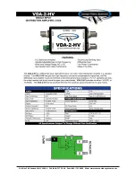
SIGNAL ADJUSTMENTS
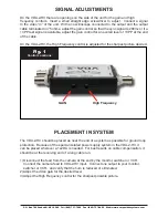
On the VDA-2-HV there are openings on the side of the unit for the gain and high
frequency controls. Insert a small straight edge screwdriver to adjust. Connect a signal
to the video “in” of the unit. With an oscilloscope connected to the output and the output
cable terminated in 75 ohms, adjust the gain control so that the sync signal is 280mv or if a
1VPP test signal is available, adjust the gain control for an overall level of 1VPP at the end
of the cable.
On the VDA-2-HV, the High Frequency control is adjusted for the sharpest picture desired.
Fig. 1
Control Locations
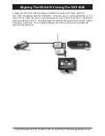
PLACEMENT IN SYSTEM
The VDA-2-HV should be placed as near the end of a system as possible for ground loop
protection. Because of the special isolated power supply system in the VDA-2-HV, it
can be placed wherever a 1x2 DA is needed. For best results on cable compensation, it
should be at the receiving end of a long cable run.
1) Disconnect the feed from the camera at the end by the monitor, switcher or VCR.
Connect the camera feed to VDA-2-HV input. Connect one output to your monitor,
switcher or VCR. and verify that the hum is reduced or eliminated.
2) Adjust the video gain for the desired level
3) Adjust the High Frequency control for the sharpest possible picture.
GAIN
High Frequency
Summary of Contents for VDA-2-HV
Page 12: ......


