


3
6. OPERATION CONTROLS AND FUNCTIONS
6.1 Transmitter Front and Rear Panels
Power
Link
CAT 5e /6 Out
DC 5V
IR2 Extender
RS232 In
IR1 Blaster
HDMI In
Rear
Front
2
3
1
5
4
6 7
8
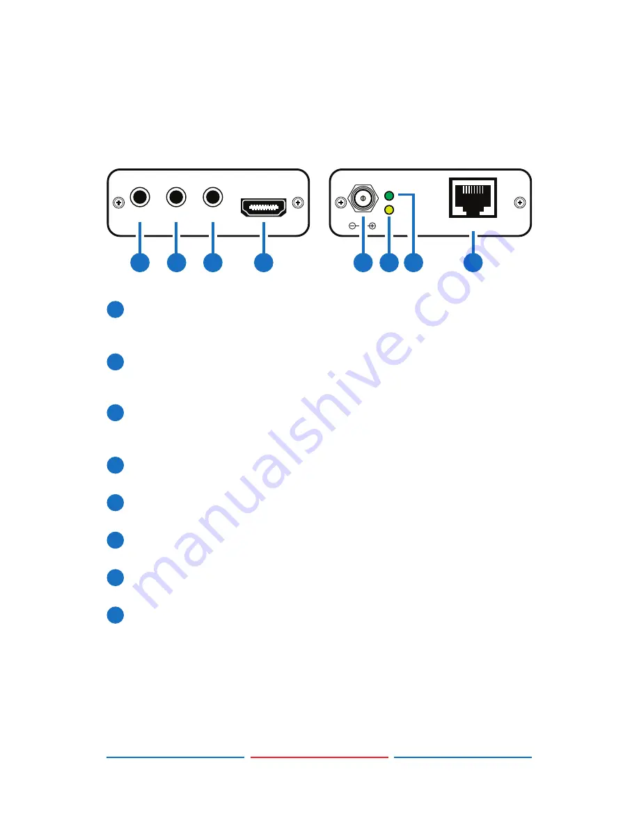
1
RS-232 In:
Connect to a PC/laptop or RS-232 enabled device(with
supplied 3.5 mm phone jack to D-Sub 9 pin adaptor) for the
transmission of RS-232 commands.
2
IR2 Extender:
Connect to the supplied IR extender cable for IR
signal reception. Ensure that remote controller being used is within
the direct line-of-sight of the IR extender.
3
IR1 Blaster:
Connect to the supplied IR blaster cable for IR signal
transmission. Place the IR blaster in direct line-of-sight of the
equipment to be controlled.
4
HDMI In:
Connect to HDMI source equipment such as a DVD or Blu-
ray player.
5
DC 5V:
Plug the 5 V DC power supply into the unit and connect the
adaptor to an AC outlet.
6
Link:
The yellow LED will illuminate when both the input and output
CAT5e/6 signals are connected.
7
Power:
This green LED will illuminate when the device is connected
to a power supply.
8
CAT5e/6 Out:
Connect to the receiver unit with a single CAT5e/6
cable for transmission of all data signals.


