background image

CARF-Models   Sukhoi   SU-31                                  

    11


Canopy Installation 

The canopy frame mounting has 
already been completed at the 
factory for you. It is held in place 
with 4 bolts (M4 x 12mm) and the 
holes are counter-bored so the 
bolt-heads sit flush with the 
fuselage surface. Fitting the clear 
canopy into the frame is a little bit 
tricky, but this is a step by step 
guide of how to do it successfully:  
Sand the inside edges of the 
canopy frame carefully with rough 
sandpaper, to ensure a perfect fit 
of the canopy inside. Lay the 
canopy on top of the frame, and 
mark the rough shape with a felt 
pen or wax crayon. Cut the outer 
border of the clear canopy with 
sharp scissors, about 12mm 
(1/2”) too big all around. Unless 
you are in a very warm room, we 
recommend the canopy is slightly 
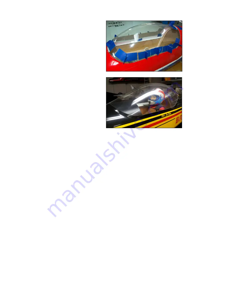
warmed up with a hair dryer to prevent cracking, but be careful not to melt or 
deform it! When the canopy fits inside the frame roughly, mark the final cut line. 
Then cut it to exact shape with a 6 - 8 mm overlap all around.  Make several hand-
holds with wide paper masking tape (see photo) to make holding and positioning 
the canopy easy.  Push the canopy up tightly inside the back of the frame and fix 
the bottom back corners with one drop of slow CA (ZAP-O or Plasti-ZAP 
recommended).  

Note: 

Do NOT use any CA accelerator/kicker - you will 

immediately ‘fog’ the clear canopy!  Tape the front of the canopy to the frame 
temporarily.  Mount the canopy frame to the fuselage (use all 4 bolts), and tape 
the back of the canopy frame tightly to the fuselage.  Using the masking tape 
handles to pull the canopy outwards firmly against the frame, working from the 
back towards the front, glue the edges of the canopy in place in 2 more places 
each side, with just a single small drop of CA at each position, all the time 
checking the edge of the canopy is tight up against the frame at the front. Make a 
visual check from the front and back to make sure the canopy is straight. Now the 
canopy is fixed in position and cannot twist or warp.  Carefully glue the canopy 
firmly in place.  You can either complete the gluing from the outside, allowing the 
CA glue to wick into the joint between the frame and the clear plastic or, if you 
prefer, you can carefully remove the canopy frame from the fuselage, and use a 
30 minute or a 24hr epoxy and micro-balloon mixture gluing all the edges to the 
frame on the inside surface. Even if you use the CA glue method, we highly 
recommend that you also glue the inside edges with the epoxy mixture to be sure 
the canopy cannot come off in flight.


Summary of Contents for CARF-Models Sukhoi SU-31

Page 1: ...CARF Models Sukhoi SU 31 Building Instructions Version 1 1...

Page 2: ...our model and we have no control over the methods you use to install operate and maintain the radio control system components For this reason we are obliged to deny all liability for loss damage or co...

Page 3: ...installation first WITHOUT the engine running Leave the transmitter antenna retracted and check the distance you can walk before fail safe occurs Then start up the engine run it at about half throttle...

Page 4: ...denaturized alcohol or equivalent before gluing parts together Milled carbon or fiberglass sandwich parts also need to be lightly sanded and cleaned before gluing in place We recommend at least 30 mi...

Page 5: ...e with hardener 6 Milled glass fiber for adding to slow epoxy for stronger joints 7 Micro balloons for adding to slow epoxy for lightweight filling 8 Thread locking compound Loctite 243 ZAP Z 42 or eq...

Page 6: ...CARF Models Sukhoi SU 31 6 Kit Contents Below are pictures of the contents of the kit after you open the box Carefully remove and inspect each piece of the kit...

Page 7: ...CARF Models Sukhoi SU 31 7 Motor Dome Extension Milled Wood Pack Fuse Hardware Pack Wing Hardware Pack Rudder Pack Stab Pack...

Page 8: ...eel mounting 2 Washer M6 ID x 13mm OD for wheel mounting 6 Allen bolts M6x20mm Landing gear plate 6 Washer M6 ID x 20mm Landing gear plate Wing pack Qnt Description 4 Plastic nut M6 4 Aluminum clevise...

Page 9: ...2 Sheet metal screw 2 9 x 16 mm to secure servos 12 Washer M3 4 All Thread M3 x 45 mm 4 Spring steel clevises M3 4 Allen bolt M3 x 16mm 4 Nuts M3 Elevator Stabs pack Quantity Description 2 Allen bolt...

Page 10: ...line Have a helper hold the gear in position and drill only the inner hole Note be sure to keep hands clear when drilling hole Drill only one hole at a time and then install the 6mm bolt and lock nut...

Page 11: ...x the bottom back corners with one drop of slow CA ZAP O or Plasti ZAP recommended Note Do NOT use any CA accelerator kicker you will immediately fog the clear canopy Tape the front of the canopy to t...

Page 12: ...se the 3mm screws provided with the kit to mount the servo not the screws that come with the servos With the servo installed as shown center the servo and install the servo arm Use the 3mm threaded ro...

Page 13: ...ully and glue the complete assembly in place with epoxy and micro balloons mixture with a nice fillet on all joints Install the 3 servos into the rudder tray using the 2 9mm x 13mm screws supplied wit...

Page 14: ...nd mechanical advantage These arms clamp onto the servo output shaft with no lost movement play at all Secure your chosen metal servo arms to the servos centering them all with your radio so the arms...

Page 15: ...wl firmly in position and drill right thru the cowl and fuselage sides with a sharp 3mm drill about 7mm from the back edge of the cowl Sand around each hole inside the fuselage and clean off the dust...

Page 16: ...pe a straight edge to the top of the fuse in the area right in front of the canopy frame Make sure it stays flat against the fuse Use a ruler to measure down from bottom of the straight edge 8 1 4 21c...

Page 17: ...ng It you intend to use the DA 200 it is very important to have proper baffling to provide adequate cooling The baffling should come right up to the cylinders and go all the way around to the back We...

Page 18: ...the equipment tray Note if you are not going to use a high current receiver like the JR 1222 then it is recommended that you use a Powerbox with two batteries There is plenty of room on the tray to m...

Page 19: ...ely There are lots of things that will influence the amount of mixing required But as an indication the only mix we required during our test flight was 5 up elevator for knife edge flight no aileron m...

Page 20: ...ht It is absolutely necessary to range check your complete R C installation first WITHOUT the engine running Leave the transmitter antenna retracted and check the distance you can walk before fail saf...

Reviews: