4.
Hardware Installation
Before setting up the Compex SDS1224, please take note of the following
after you have unpacked the unit:
•
Ensure that there is sufficient space for heat ventilation when
placing it near to a power outlet.
•
Ensure that the mounting surface to place Compex SDS1224
should be free of grease and dust.
•
Ensure that there is enough spacing around the unit to allow
attachment of network cables.
1.
Attach the rubber feet on the
bottom of the metal chassis.
These rubber feet prevent the
switch from shock and vibration.
2.
Since Compex SDS1224 comes
with a rack mount kit, position
one bracket to align with the
holes on one side of the switch
and secure it with the smaller
bracket screws.
3.
Attach the remaining bracket to
the other side of the switch.
4.
After both the mounting
brackets are attached, position
the switch in the rack by lining
up the holes in the brackets with
the appropriate holes on the
rack.
5.
Secure the switch to the rack
with a screwdriver and the rack-
mounting screws.
6.
Connect the power cord to the power socket on the rear panel of the
switch. The other side of power cord connects to the power outlet.
7.
Use a RJ45 Ethernet cable and connect it to any of the ports.
(according to the examples in the Network Application ).
8.
The hardware setup is done. You may power on the device now. Check
the power indicator on the front panel to see if power is properly
supplied.
5.
Panel View Description
Figure 3 Front view of Compex SDS1224
Figure 4 Rear view of Compex SDS1224
Indicator
Description
n
Power LED
If the LED shows GREEN, it means that power is supplied
to the unit. Otherwise no power is supplied to the unit if
the LED turns OFF.
o
LED Indicators
Used for real-time information of system operation status.
For more details, refer to LED Indicators Description.
p
24 RJ45 10/100
Mbps Ports (
Auto MDI/MDIX)
Use UTP/STP network cables to connect
10 Base-T or 100 Base-TX
Auto negotiable feature
(Take note that MDI means connecting to another hub
or switch while MDIX means connecting to a workstation
or PC. So Auto MDI/MDIX means that you can connect
to another switch or workstation without changing non-
crossover or crossover cabling).
q
Power Socket
Power input at the range of 100-240V AC, 50-60Hz.
6.
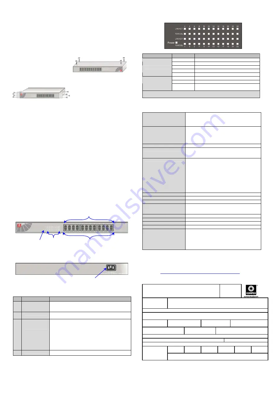
LED Indicators Description
LED Indicator
Status
Description
Green Power
On
Power
Off
Power is not connected.
Green
The port is connecting with the device.
Blinks
The port is receiving or transmitting data.
LNK/ACT
Off
No device is attached.
Orange
The port is operating in Full Duplex mode.
Blinks
Collision of Packets occurs in the port.
FD/COL
OFF
No device is attached. Or it operates in
half-duplex mode.
LNK/ACT means Link/Activity.
FD/COL means Full Duplex/Collision of data
7.
Hardware Specification
EMI & Safety
FCC Part 15 Class A
CE Mark
UL & cUL
CE/EN60950
Standards supported
Complies with
IEEE 802.3: 10Base-T Ethernet
IEEE 802.3u: 100Base-Tx Fast Ethernet
IEEE 802.3x: Flow Control and Back-Pressure
IEEE 802.1P: Network Traffic Prioritization
Technology
Store and Forward Switching Architecture
LED Indicators
Power
Link/Activity
Full Duplex/Collision
Network Media
10Base-T:
o
2-pair UTP/STP Category 3, 4, 5.
o
EIA/TIA-568 100-ohm.
o
Maximum length: 100 meter
100Base-TX:
o
2-pair UTP/STP Category 5.
o
EIA/TIA-568 100-ohm
o
Maximum length: 100 meter
Protocol
CSMA/CD
Memory Buffer
1.25Mbits
MAC Address
4K MAC address table
Transfer Rate
14,880 pps per Ethernet port
148,800 pps per Fast Ethernet port
Backplane
4.8 Gbps
Power Consumption
Maximum of 18 watts
Power Supply
100-240V AC, 50-60Hz
Dimension
440mm x 120mm x 44mm (L x W x H)
Environment Requirements
Operating Temperature:
Storage Temperature:
Operating Humidity:
0
°
C to 45
°
C
-10
°
C to 70
°
C
10% to 90%
(Non-condensing)
p
WARRANTY REGISTRATION CARD
[M-0088-V2.3C]
You can
register via
Internet at:
http://www.cpx.com
or
http://www.compex.com.sg
Or E-mail: [email protected] with the following information:
To activate the warranty, please complete this card and return to Compex within ninety
(90) days of purchase date.
Product:
Purchase Date:
Model:
Serial No:
Name: Title:
E-mail:
Address:
Postal/Zip Code:
Country:
Phone: ( )
Work
Friend
Internet
Dealer
Magazine
Exhibition
How did you
learn about
Compex?
Other:
Note:
For purchases within U.S.A and Canada, please fax to Compex, Inc. at (714) 630-6521
For purchases outside U.S.A and Canada, please fax to Compex Systems Pte Ltd at (65)
6280-9947
n
p
o
Further Information References
If you have other Windows operating systems or broadband Internet accounts,
please refer to the User’s Manual in the accompanying Product CD.
This document may become superseded, in which case you may find its latest
version at:
http://www.compex.com.sg/prodspec.asp?f=Manual&s=1
q
--
a
long the dotted line-----
-
---
---Cut along the dotted line----
--
---
--- Cut
along the dotted line-----
--
-----Cut along the dotted line-----
-----Cut along the dotted line-----
-----Cut along the dotted line-----
----


