


4–16
Compaq Prosignia Desktop 340 Series Computer
Removal and Replacement Procedures
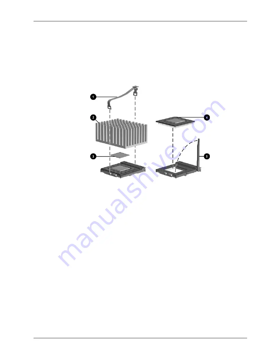
4.10 Processor
1. Perform the preparation procedures.
2. Remove the hood.
3. Remove the power supply. (Section 4.3)
4. Locate the heatsink
2
on the system board.
5. Remove the clip
1
from the heatsink.
6. Carefully remove the heatsink from the processor
4
by twisting it before lifting it from the
socket (the two are held together by an adhesive strip
8
). Never lift the heatsink straight up
from the processor as it may pull the processor from its socket and damage its pins.
7. Tilt the ZIF socket handle
5
away from the system board.
8. Lift the processor directly out of the ZIF socket.
To replace the processor, reverse this sequence.
Summary of Contents for Prosignia Desktop 340 Series
Page 10: ...2 2 Compaq Prosignia Desktop 340 Series Computer Spare Parts 2 1 System Unit...
Page 12: ...2 4 Compaq Prosignia Desktop 340 Series Computer Spare Parts 2 2 Mass Storage Devices...
Page 14: ...2 6 Compaq Prosignia Desktop 340 Series Computer Spare Parts 2 3 Cables...
Page 16: ...2 8 Compaq Prosignia Desktop 340 Series Computer Spare Parts 2 4 Standard and Optional Boards...
Page 20: ...2 12 Compaq Prosignia Desktop 340 Series Computer Spare Parts...
Page 48: ...4 22 Compaq Prosignia Desktop 340 Series Computer Removal and Replacement Procedures...
Page 52: ...5 4 Compaq Prosignia Desktop 340 Series Computer System Board Jumpers and Switches...
Page 56: ...Compaq Prosignia Desktop 340 Series Computer Index 4 Index...


