Compaq Presario 300 - Notebook PC Maintenance And Service Manual Download Page 46

Compaq Presario Series Maintenance and Service Guide 

United States     December 9, 2002

Presario 305 Model

Before You Begin

Specifications

Parts Catalog

Removal Sequence

Troubleshooting

Battery Operations

Product Description

Pin Assignments

Index

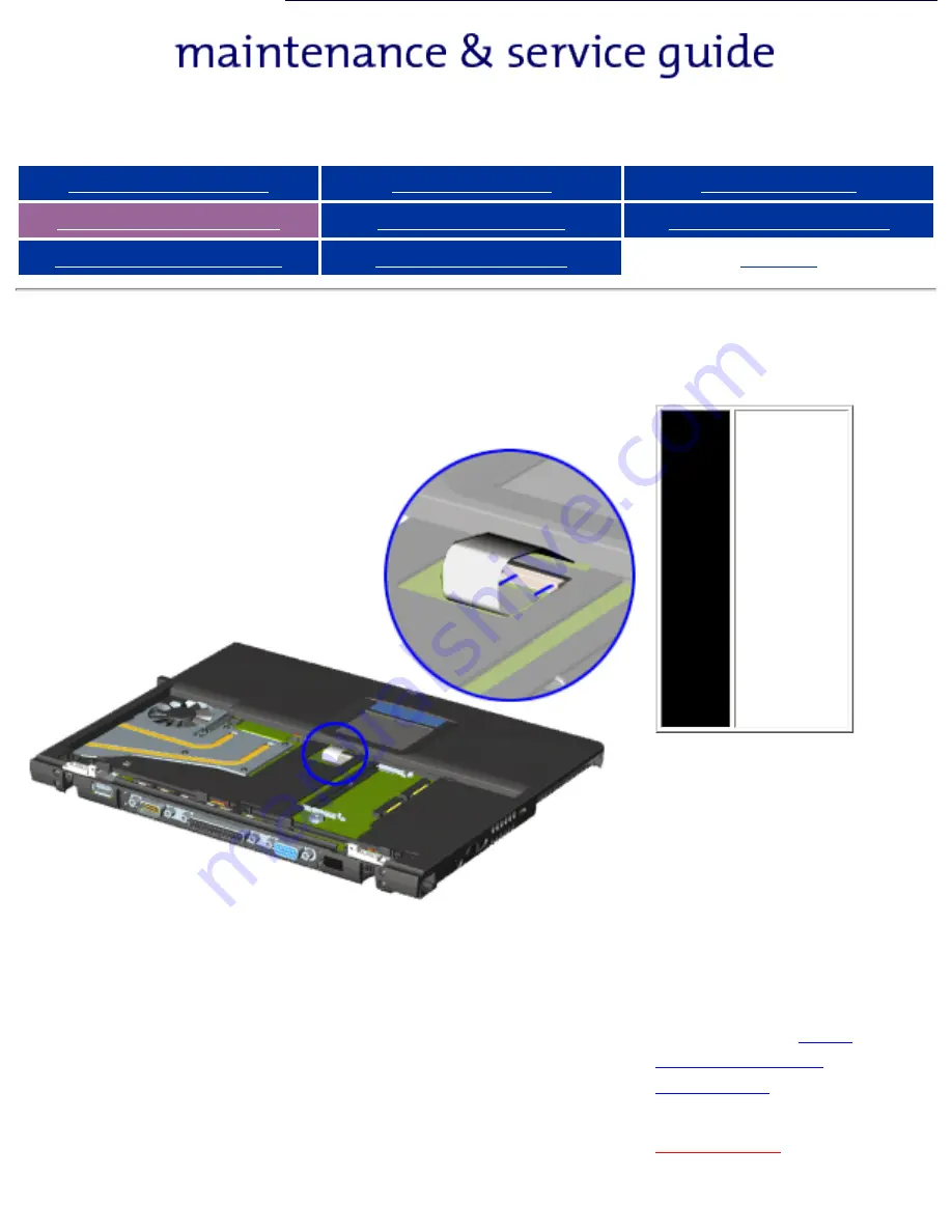
Removing the Deck (continued)

NOTE:

The 

touchpad is 

spared 

with the 

deck. It is 

not 

available 

separately. 

This guide 

does not 

contain 

instructions 

for its 

removal.

7. Turn the 

computer right side 

up with the front 

facing forward.

8. Disconnect the 

touchpad cable from 

the system board.

The touchpad cable 

is a flat ribbon cable 

secured with a 

Zero 

Insertion Force 
Connector.

Next step


privacy and legal statement

http://h18000.www1.hp.com/athome/support/msgs/305/deckre3.html [12/9/2002 2:19:05 PM]

Summary of Contents for Presario 300 - Notebook PC

Page 1: ...Removal Replacement Procedures Specifications Connector Pin Assignments Battery Pack Operations See Notice for copyright and trademark information and see Preface for symbol conventions Technician Notes and Serial Number locations on the unit This MSG will be periodically maintained and updated as needed To report a technical problem contact your Regional Support Center or IM Help Center For conte...

Page 2: ... without prior written consent from Compaq Computer Corporation 1999 Compaq Computer Corporation All rights reserved Printed in the U S A Compaq and Presario are registered in the U S Patent and Trademark Office Microsoft MS DOS Windows and Windows NT are registered trademarks of Microsoft Corporation Windows 98 is a trademark of Microsoft Corporation The software described in this guide is furnis...

Page 3: ...is equipment All troubleshooting and repair procedures are detailed to allow only subassembly module level repair Because of the complexity of the individual boards and subassemblies the user should not attempt to make repairs at the component level or to make modifications to any printed circuit board Improper repairs can create a safety hazard Any indications of component replacement or printed ...

Page 4: ...Unit Rear Connectors Multi media Expansion Unit Power Management for Windows 98 The Compaq Presario 305 Computer provides industry leading features in a uniquely designed ultraportable The ultra light 3 1 to 3 3 pound 1 4 to 1 5 kg notebook depending on configuration allows users high mobility and provides a full set of system ports When paired with the Mobile Expansion Unit MEU the Presario 305 c...

Page 5: ...t Side Components Right Side Components Bottom of Unit Rear Connectors Multi media Expansion Unit Power Management for Windows 98 Compaq Presario 305 Model Portable Computer Display 11 3 inch Color TFT Display Processor 333 MHz Celeron II with 128k integrated cache Hard Drive 4 3 GB Total System Memory 64 MB SDRAM 128 MB SDRAM Maximum CD Drive 24x Modem 56 Kbps V 90 PCI Battery High Capacity Li Io...

Page 6: ... Components Left Side Components Right Side Components Bottom of Unit Rear Connectors Multi media Expansion Unit Power Management for Windows 98 1 Display Release Latch 2 Display 3 Hard Drive Light 4 Diskette Drive Light 5 Scroll Lock Light 6 Caps Lock Light 7 Num Lock Light 8 Standby Button 9 Instant Internet Access Button 10 Instant Search Access Button 11 E Commerce Button 12 Instant E Mail But...

Page 7: ... Operations Product Description Pin Assignments Index Front Components Models and Features Upper Unit Components Front Components Left Side Components Right Side Components Bottom of Unit Rear Connectors Multi media Expansion Unit Power Management for Windows 98 1 Battery Light 2 Power Suspend Light 3 Microphone Jack 4 Stereo Speaker Headphone Jack 5 Touch Pad privacy and legal statement ...

Page 8: ...ting Battery Operations Product Description Pin Assignments Index Left Side Components Models and Features Upper Unit Components Front Components Left Side Components Right Side Components Bottom of Unit Rear Connectors Multi media Expansion Unit Power Management for Windows 98 1 Power Connector 2 Power Button 3 Security Cable Slot 4 Hard Drive Bay privacy and legal statement ...

Page 9: ...y Operations Product Description Pin Assignments Index Right Side Components Models and Features Upper Unit Components Front Components Left Side Components Right Side Components Bottom of Unit Rear Connectors Multi media Expansion Unit Power Management for Windows 98 1 PC Card Slot 2 PC Card Eject Lever 3 Air Intake Exhaust Vents 4 Modem Connector RJ 11 jack privacy and legal statement ...

Page 10: ...ription Pin Assignments Index Bottom of Unit Models and Features Upper Unit Components Front Components Left Side Components Right Side Components Bottom of Unit Rear Connectors Multi media Expansion Unit Power Management for Windows 98 1 Battery Latches 2 Real time Clock Battery 3 Bottom of fan Fan removable from inside only 4 Speaker 5 Modem Compartment 6 220 pin Docking Connector privacy and le...

Page 11: ...ons Product Description Pin Assignments Index Rear Connectors Models and Features Upper Unit Components Front Components Left Side Components Right Side Components Bottom of Unit Rear Connectors Multi media Expansion Unit Power Management for Windows 98 1 USB Connector 2 Serial Connector 3 Parallel Connector 4 External Monitor Connector 5 Infrared Port 6 Battery Pack privacy and legal statement ...

Page 12: ...Assignments Index Multi media Expansion Base Models and Features Upper Unit Components Front Components Left Side Components Right Side Components Bottom of Unit Rear Connectors Multi media Expansion Unit Power Management for Windows 98 1 Docking Alignment Tabs 2 Docking Connector 3 Audio output 4 Audio input 5 Docking Release Button 6 Speaker 7 Multibay Eject Lever 8 CD or DVD 9 Diskette Drive pr...

Page 13: ...l maintain system information and open files Unsaved information will be lost if you turn off your system prior to system wake up or if you lose power while using the AC adapter Hibernation Mode Hibernation helps conserve battery life and protects your data Hibernation can be a routine power saving event or can be the result of a low battery condition As it enters Hibernation your computer will di...

Page 14: ... Display Panel Deck Voltage Converter Board Modem Connector Board PC Card PC Card Assembly System Board To remove the battery pack complete the following steps WARNING To reduce the risk of injury or damage to the battery pack do not crush puncture or incinerate the battery pack or short the metal contacts Do not attempt to open or service the battery pack 1 Remove the Multi media Expansion Unit 2...

Page 15: ...Index Removing the Battery Pack continued 4 Rotate the battery pack into a vertical position 1 and lift up the battery pack from the computer 2 To replace the battery pack reverse the removal procedures WARNING To prevent damage to the computer do not insert a battery pack until the computer is fully reassembled Back to step 1 privacy and legal statement http h18000 www1 hp com athome support msgs...

Page 16: ...Cover Display Panel Deck Voltage Converter Board Modem Connector Board PC Card PC Card Assembly System Board To remove the Multi media Expansion Unit complete the following steps 1 Prepare the computer for disassembly 2 Turn off and disconnect all external devices connected to the computer 3 On the Multi media Expansion Unit press the docking release button 1 to release the expansion unit from the...

Page 17: ...sassembly Electrostatic Discharge Service Considerations Cables and Connectors Multi media Expansion Unit Battery Pack Hard Drive Modem Card RTC Battery Keyboard Memory Board Switch Cover Display Panel Deck Voltage Converter Board Modem Connector Board PC Card PC Card Assembly System Board Report the serial number to Compaq when requesting information on ordering spare parts located on the undersi...

Page 18: ...partment To prevent damage do not allow metal objects to touch the battery contacts Place only the battery pack for the Compaq Presario 305 Model Portable Computers into the battery compartment Do not force the battery pack into the bay if insertion does not occur easily CAUTION Do not crush puncture or incinerate the battery pack Do not open a battery pack as this damages the pack makes it unusab...

Page 19: ...enough power to alter device parameters or melt silicon junctions Generating Static The table shows how different activities generate static electricity and at different electrostatic voltage levels Typical Electrostatic Voltages Relative Humidity Event 10 40 55 Walking across carpet 35 000 V 15 000 V 7 500 V Walking across vinyl floor 12 000 V 5 000 V 3 000 V Motions of bench worker 6 000 V 800 V...

Page 20: ...moval Sequence Serial Number Location Preparing for Disassembly Electrostatic Discharge Service Considerations Cables and Connectors Multi media Expansion Unit Battery Pack Hard Drive Modem Card RTC Battery Keyboard Memory Board Switch Cover Display Panel Deck Voltage Converter Board Modem Connector Board PC Card PC Card Assembly System Board Report the computer serial number located on the bottom...

Page 21: ...er Diagnostics software Screws The screws used in the computer are not interchangeable If an incorrect screw is used during the reassembly process it can damage the unit Compaq strongly recommends that all screws removed during disassembly be kept with the part that was removed then returned to their proper locations Fan and RJ11 The Fan and RJ11 are spared with the base assembly They are not avai...

Page 22: ...bending twisting or pulling on the cables Apply minimum required force when seating or unseating the cables from their connectors Place the cables in such a manner that they cannot be caught or snagged by parts being removed or replaced Handle flex cables with extreme care they can tear easily CAUTION When servicing these computers ensure that cables are placed in their proper location during the ...

Page 23: ...r uses a zero insertion force ZIF connector for several cable connections on the system board To remove a ZIF cable from its connector pull both ends of the ZIF cable guide clasp out of the sleeve about 0 05 0 1 1 2 mm then gently slide the cable out CAUTION A ZIF connector and its attached cable can be easily damaged Never pull or twist on the cable while it is connected CAUTION Ensure that cable...

Page 24: ...sario 305 Model Before You Begin Specifications Parts Catalog Removal Sequence Troubleshooting Battery Operations Product Description Pin Assignments Index Display Panel Cable Location Note the location of the display panel cable Back to Cables and Connectors privacy and legal statement ...

Page 25: ...2 Presario 305 Model Before You Begin Specifications Parts Catalog Removal Sequence Troubleshooting Battery Operations Product Description Pin Assignments Index Inverter Cable Location Note the location of the inverter cable Back to Cables and Connectors privacy and legal statement ...

Page 26: ...2002 Presario 305 Model Before You Begin Specifications Parts Catalog Removal Sequence Troubleshooting Battery Operations Product Description Pin Assignments Index Audio Cable Location Note the location of the audio cable Back to Cables and Connectors privacy and legal statement ...

Page 27: ...ns Parts Catalog Removal Sequence Troubleshooting Battery Operations Product Description Pin Assignments Index Touchpad Cable Location Note the location of the touchpad cable The touchpad cable is a flat ribbon cable that attaches by means of a Zero Insertion Force Connector Back to Cables and Connectors privacy and legal statement ...

Page 28: ...9 2002 Presario 305 Model Before You Begin Specifications Parts Catalog Removal Sequence Troubleshooting Battery Operations Product Description Pin Assignments Index Fan Cable Location Note the location of the fan cable Back to Cables and Connectors privacy and legal statement ...

Page 29: ...io 305 Model Before You Begin Specifications Parts Catalog Removal Sequence Troubleshooting Battery Operations Product Description Pin Assignments Index Light Board Cable Location Note the location of the light board cable connection Back to Cables and Connectors privacy and legal statement ...

Page 30: ...02 Presario 305 Model Before You Begin Specifications Parts Catalog Removal Sequence Troubleshooting Battery Operations Product Description Pin Assignments Index Speaker Cable Location Note the location of the speaker cable Back to Cables and Connectors privacy and legal statement ...

Page 31: ...305 Model Before You Begin Specifications Parts Catalog Removal Sequence Troubleshooting Battery Operations Product Description Pin Assignments Index Battery Cable Location Note the location of the battery cable There is one on each end Back to Cables and Connectors privacy and legal statement ...

Page 32: ...erations Cables and Connectors Multi media Expansion Unit Battery Pack Hard Drive Modem Card RTC Battery Keyboard Memory Board Switch Cover Display Panel Deck Voltage Converter Board Modem Connector Board PC Card PC Card Assembly System Board To remove the hard drive complete the following steps NOTE Before removing a hard drive back up all information on the hard drive 1 Remove the Multi media Ex...

Page 33: ... Specifications Parts Catalog Removal Sequence Troubleshooting Battery Operations Product Description Pin Assignments Index Removing the Hard Drive continued 2 Push down on the front bezel of the hard drive 1 and pull the hard drive from the bay 2 To replace the hard drive reverse the removal procedures Back to step 1 ...

Page 34: ... Connectors Multi media Expansion Unit Battery Pack Hard Drive Modem Card RTC Battery Keyboard Memory Board Switch Cover Display Panel Deck Voltage Converter Board Modem Connector Board PC Card PC Card Assembly System Board To remove the modem card complete the following steps 1 Remove the Multi media Expansion Unit 2 Turn the computer upside down front facing forward 3 Remove two screws t8 from t...

Page 35: ...ng Battery Operations Product Description Pin Assignments Index Removing the Modem Card continued 5 Lift up the back of the modem card and disconnect it from the system board 1 6 Disconnect cable connected to the modem card 2 To replace the modem card reverse the removal procedures Back to step 1 ...

Page 36: ...rd RTC Battery Keyboard Memory Board Switch Cover Display Panel Deck Voltage Converter Board Modem Connector Board PC Card PC Card Assembly System Board To remove the RTC battery complete the following steps 1 Remove the Multi media Expansion Unit 2 Turn the computer upside down with the back of the computer facing forward 3 Remove the RTC battery cover by lifting the cover at the indention 4 Remo...

Page 37: ...tic Discharge Service Considerations Cables and Connectors Multi media Expansion Unit Battery Pack Hard Drive Modem Card RTC Battery Keyboard Memory Board Switch Cover Display Panel Deck Voltage Converter Board Modem Connector Board PC Card PC Card Assembly System Board To remove the keyboard complete the following steps 1 Lift the display panel to open the computer 2 Gently press down on each of ...

Page 38: ...x Removing the Keyboard continued 3 Lift the keyboard along the bottom edge to raise at a 45 degree angle from the computer 4 Turn keyboard upside down 5 Using a connector removal tool disconnect the ZIF connector from the system board 6 Disconnect the keyboard cable from the system board To replace the keyboard reverse the removal procedures Back to step 1 ...

Page 39: ...pansion board can damage the equipment and expose you to the risk of electrical shock CAUTION Electrostatic discharge ESD can damage electronic components Before beginning this procedure ensure that you are properly grounded For more information refer to Electrostatic discharge section NOTE There is only one memory expansion slot in the computer Before upgrade memory you must remove the memory boa...

Page 40: ...k Hard Drive Modem Card RTC Battery Keyboard Memory Board Switch Cover Display Panel Deck Voltage Converter Board Modem Connector Board PC Card PC Card Assembly System Board NOTE When removing the switch cover be careful not to lose the keyboard retention spring tabs located on the top cover 1 Remove the Multi media Expansion Unit 2 Remove the battery pack 3 Remove the keyboard 4 Position the comp...

Page 41: ... continued 5 Position the computer so the front faces forward 6 Open the display panel as far as possible 7 Remove one screw from each end cap on the display panel 8 Lift the front edge of the switch cover When the switch cover disconnects from the top cover turn the back edge of the switch cover up and forward To replace the switch cover reverse the removal procedures Back to step 1 ...

Page 42: ...ssembly Electrostatic Discharge Service Considerations Cables and Connectors Multi media Expansion Unit Battery Pack Hard Drive Modem Card RTC Battery Keyboard Memory Board Switch Cover Display Panel Deck Voltage Converter Board Modem Connector Board PC Card PC Card Assembly System Board 1 Remove the battery pack 2 Remove the keyboard 3 Remove the switch cover 4 Disconnect the display panel cable ...

Page 43: ...ments Index Removing the Display Panel continued NOTE When these four screws are removed the display assembly is unsupported Make sure to support the display assembly when removing these screws 5 Remove four hinge screws t8 that secure the display assembly to the base assembly To replace display panel reverse the removal procedures Back to step 1 ...

Page 44: ...oard Memory Board Switch Cover Display Panel Deck Voltage Converter Board Modem Connector Board PC Card PC Card Assembly System Board NOTE The power switch and infrared lens are easily dislodged when the top cover is removed Make note of their location and orientation before removing the top cover The power switch and infrared lens are spared in the miscellaneous plastics kit 1 Remove the keyboard...

Page 45: ...Presario 305 Model Before You Begin Specifications Parts Catalog Removal Sequence Troubleshooting Battery Operations Product Description Pin Assignments Index Removing the Deck continued 5 Turn the computer upside down 6 Remove seven screws t8 from the underside of the unit Next Step ...

Page 46: ...ng the Deck continued NOTE The touchpad is spared with the deck It is not available separately This guide does not contain instructions for its removal 7 Turn the computer right side up with the front facing forward 8 Disconnect the touchpad cable from the system board The touchpad cable is a flat ribbon cable secured with a Zero Insertion Force Connector Next step ...

Page 47: ...fications Parts Catalog Removal Sequence Troubleshooting Battery Operations Product Description Pin Assignments Index Removing the Deck continued 9 Press in on the front of the deck 1 and pull up on deck to swing front edge up and away from the base assembly 2 To replace the deck reverse the removal procedures Back to step 1 ...

Page 48: ... Electrostatic Discharge Service Considerations Cables and Connectors Multi media Expansion Unit Battery Pack Hard Drive Modem Card RTC Battery Keyboard Memory Board Switch Cover Display Panel Deck Voltage Converter Board Modem Connector Board PC Card PC Card Assembly System Board 1 Remove the keyboard 2 Remove the switch cover 3 Remove the display 4 Remove the deck 5 Remove the two screws that se...

Page 49: ...in Assignments Index Removing the Voltage Converter Board continued 6 Lift up the left side of the voltage converter board until it clears the edge of the base assembly 7 Pull the voltage converter board to the left and disconnect it from the system board To replace the voltage converter board reverse the removal procedures Back to step 1 ...

Page 50: ...Battery Pack Hard Drive Modem Card RTC Battery Keyboard Memory Board Switch Cover Display Panel Deck Voltage Converter Board Modem Connector Board PC Card PC Card Assembly System Board To remove the modem connector board complete the following steps 1 Remove the modem card 2 Remove the keyboard 3 Remove the switch cover 4 Remove the display 5 Remove the deck 6 Remove two screws from the modem conn...

Page 51: ...To remove the PC Card complete the following steps CAUTION If the computer is on and running Windows 95 failure to stop a PC Card before removing it may cause loss of data In Windows 95 or Windows 98 If the computer is on stop the PC Card before you remove it To stop a PC Card select the PC Card icon in the taskbar then select the PC Card you want to stop A message displays when the PC Card can be...

Page 52: ...el Deck Voltage Converter Board Modem Connector Board PC Card PC Card Assembly System Board 1 Remove the modem card 2 Remove the keyboard 3 Remove the switch cover 4 Remove the display 5 Remove the deck 6 Remove the modem connector board 7 Remove the two silver t8 screws on the left side of the PC card assembly 8 Remove the black t8 screw that secures the front of the PC card assembly to the base ...

Page 53: ...ck Voltage Converter Board Modem Connector Board PC Card PC Card Assembly System Board NOTE There are different sized screws securing the system board to the base enclosure Make note of the location of these screws Also when the system board is removed components of the base enclosure tend to fall loose Note the location and orientation of all base enclosure components 1 Remove the RTC battery 2 R...

Page 54: ...fications Parts Catalog Removal Sequence Troubleshooting Battery Operations Product Description Pin Assignments Index Removing the System Board continued 9 Disconnect the speaker cable 1 light indicator board cable 2 fan cable 3 upper left battery cable 4 and upper right battery cable 5 Next step privacy and legal statement ...

Page 55: ... Description Pin Assignments Index Removing the System Board continued 9 Remove the four screws on the back of the computer that secure the system board to the base assembly 10 Lift up the back edge of the system board making sure to route the battery terminal cables through the spaces in the hinge cradles To replace the system board reverse the removal procedures Back to step 1 privacy and legal ...

Page 56: ...ompaq Presario 305 Model Portable Computer The basic steps in troubleshooting include 1 Follow the Preliminary Steps 2 Run the Power On Self Test POST 3 Follow the recommended actions described in the diagnostic tables if you are unable to run POST or if POST displays an error message When following the recommended actions in the Sections on POST and Diagnostic Error Codes perform them in the orde...

Page 57: ...ery pack is installed in the computer and the power cord is connected to the computer and plugged into an external AC power source 4 Turn on the computer 5 Run Computer Setup 6 Turn off the computer and its external devices 7 Disconnect any external devices that you do not want to test If you want to use the printer to log error messages leave it connected to the computer IMPORTANT If the problem ...

Page 58: ...oller Power On Self Test Messages 102 System Board Failure Probable Cause Recommended Action DMA timers etc Replace the system board 162 System Options Not Set Probable Cause Recommended Action Configuration incorrect Run Computer Setup CMOS reflects that an invalid configuration has been set Run Computer Setup XX000YZZ 201 Memory Error Probable cause Recommended action RAM failure 1 Replace the m...

Page 59: ...ing the RTC battery located on the system board as follows 1 Turn off the computer 2 Disconnect the AC Adapter 3 Remove the Multi media Expansion Unit 4 Remove the battery pack 5 Disconnect and remove the RTC battery 6 Wait for five minutes 7 Reconnect the RTC battery 8 Reconnect the AC Adapter Do not reinstall the battery pack yet 9 Turn on the computer to verify that the power on password has be...

Page 60: ...test 4 Insert the Compaq Diagnostics diskette in drive A 5 Turn on or restart the computer The computer starts from drive A and the Diagnostics Welcome screen appears 6 Press Enter to continue The Diagnostics menu appears 7 Select Computer Checkup from the Diagnostics menu A Test Option menu appears 8 Select View the Device List from the Test Option menu A list of the installed Compaq devices appe...

Page 61: ...p TEST Printed copies of CONFIG SYS and AUTOEXEC BAT files if possible Shipping Preparation To ship the computer complete the following steps 1 Back up the critical hard drive files Ensure that backup tapes diskette are not exposed to electrical or magnetic fields while stored in transit 2 Turn off the computer and external devices 3 Disconnect the external devices from their power sources then fr...

Page 62: ...ogrammable timer load data test failed 113 xx Protected mode test failed Memory Test Error Codes 200 xx Memory machine ID test failed 1 Flash the system CMOS and retest 2 Replace the system board and retest 202 xx Memory system CMOS checksum failed 203 xx Write Read test failed Remove and replace the memory board or system board if memory board on the system board is faulty and retest 204 xx Addre...

Page 63: ...st failed 507 xx Video 40 25 mode test failed 511 xx Video screen memory page test failed 512 xx Video gray scale test failed 514 xx Video white screen test failed 516 xx Video noise pattern test failed 2402 xx Video memory test failed The following steps apply to error codes 2402 xx through 2456 xx 1 Run Compaq Utilities 2 Disconnect external monitor and test with internal LCD display 3 Replace t...

Page 64: ...ures disconnect all power sources before removing the keyboard cover or the display bezel Before Replacing Parts When troubleshooting a problem check the following items for possible solutions before replacing parts Verify that cables are connected properly to the suspected defective parts Verify that all required device drivers are installed Verify that all printer drivers have been installed for...

Page 65: ...sed to extremely cold temperatures Put the computer in a warmer place and recharge the battery pack Keep the battery pack within the recommended temperature ranges Operating 50 F to 104 F 10 C to 40 C Storage 32 F to 86 F 0 C to 30 C Battery conservation is disabled or set to drain Reset the battery conservation level An external device is draining the battery Turn off or remove any external devic...

Page 66: ...ce the system board Backlight brightness cannot be adjusted with Fn F7 or Fn F8 Improper display cable connections 1 Reseat the display cable to the system board 2 Replace the display assembly Defective inverter board Replace the display assembly Defective display cable Replace the display assembly Defective system board Replace the system board Contrast cannot be adjusted with Fn F5 or Fn F6 Impr...

Page 67: ... Replace the battery pack Connect the computer to an external power source Battery is discharged and cables to the external power source are unplugged Ensure that cables connecting the computer and external power source are plugged properly Computer turned off while it was left unattended Computer initiated because of a critical low battery condition Charge the battery pack Replace the battery pac...

Page 68: ...e the number of connected external USB devices to no more than two hubs on the first tier and no more than one keyboard and one pointing device on the first or second tier External devices in lower tiers do not work An unpowered hub is connected to another unpowered hub Use only powered hubs Make sure that all unpowered hubs are immediately preceded by powered hubs in the USB chain Modem Problems ...

Page 69: ...least every 30 days to improve overall battery performance Keep a battery pack in the computer when using it with AC power to supply the battery pack with a constant trickle charge Store the battery pack in a cool dry place when not in use Conditioning a Battery Pack CAUTION To avoid a loss of data ensure that all data is saved before discharging a battery pack To condition a battery pack complete...

Page 70: ... Auto Linefeed 6 Data Bit 4 15 Error 7 Data Bit 5 16 Initialize Printer 8 Data Bit 6 17 Select In 9 Data Bit 7 18 25 Signal Ground Active low Serial Connector Connector Pin Signal 1 2 3 4 5 6 7 8 9 Carrier Detect Receive Data Transmit Data Data Terminal Ready Signal Ground Data Set Ready Ready to Send Clear to Send Ring Indicator Keyboard Mouse Connector Pin Signal 1 2 3 4 5 6 Data 1 Clock 2 Groun...

Page 71: ...ents Index Illustrated Parts Catalog System Components System Unit External Cables Miscellaneous Plastics Kit Screw Kit Miscellaneous Parts Documentation and Software This section provides illustrated parts and a reference for spare parts numbers for Compaq Presario 305 Series Personal Computers When requesting information or ordering spare parts the computer serial number should be provided to Co...

Page 72: ...External Cables Miscellaneous Plastics Kit Screw Kit Miscellaneous Parts Documentation and Software Description Spare Part Number 1 Switch Cover spared with miscellaneous plastics kit 146634 001 2 Keyboard 3 Top Cover with Touchpad 146632 001 4 System Board with 333Mhz Celeron Processor 152606 001 5 Modem Connector 140385 001 6 Voltage Converter 136251 001 7 PC Card Assembly 140384 001 8 Hard Driv...

Page 73: ...scription Pin Assignments Index Illustrated Parts Catalog System Components System Unit External Cables Miscellaneous Plastics Kit Screw Kit Miscellaneous Parts Documentation and Software Description Part Number 1 Display Panel 146631 001 2 Battery Pack 146630 001 3 Multi media Expansion Base 146635 001 4 AC Adapter 101898 001 ...

Page 74: ...oduct Description Pin Assignments Index Illustrated Parts Catalog System Components System Unit External Cables Miscellaneous Plastics Kit Screw Kit Miscellaneous Parts Documentation and Software Description Part Number 1 AC Power Cord 2 Modem Cable 307366 001 3 Diskette Drive Cable 140383 001 privacy and legal statement http h18000 www1 hp com athome support msgs 305 xtrcbl html 12 9 2002 2 22 44...

Page 75: ... Parts Catalog System Components System Unit External Cables Miscellaneous Plastics Kit Screw Kit Miscellaneous Parts Documentation and Software Description Part Number Miscellaneous Plastics Kit 146634 001 1 Rubber tabs 2 USB cover 3 RTC battery 4 RTC battery cover 5 Switch cover 6 Rubber feet 7 Modem combo card door 8 Power button 9 Expansion base connector door upper 10 Expansion base connector...

Page 76: ...ng Battery Operations Product Description Pin Assignments Index Illustrated Parts Catalog System Components System Unit External Cables Miscellaneous Plastics Kit Screw Kit Miscellaneous Parts Documentation and Software Description Part Number 1 Misc Screw Kit 136255 001 privacy and legal statement http h18000 www1 hp com athome support msgs 305 screw html 12 9 2002 2 22 49 PM ...

Page 77: ...m Components System Unit External Cables Miscellaneous Plastics Kit Screw Kit Miscellaneous Parts Documentation and Software Description Part Number 1 Diskette Drive 140383 001 2 Diskette Drive 1 44MB 149372 001 3 24x CD ROM 152957 001 4 4xDVD 152958 001 5 32MB Memory 135242 001 6 64MB Memory 135243 001 7 128MB Memory 135244 001 8 56Kpbs V 90 PCI Modem 121896 001 privacy and legal statement http h...

Page 78: ...Software Description Part Number Quick Restore CD Quick Reference Guide single issue Quick Reference Guide quarterly subscription QuickFind for Windows Return Kit 136257 001 QuickFind is updated monthly To complete the QuickFind part number add the suffix from the table below for the desired month If you do not specify the 3 digit suffix the default is the current month in which the order is place...

Page 79: ...km Shock Operating Non operating 10 G 11 ms half sine 60 G 2 ms half sine Vibration Operating Nonoperating 0 25 G 50 to 500 Hz sine 1 2 Oct Min sweep rate 1 G 50 to 500 Hz sine 1 2 Oct Min sweep rate NOTE Applicable product safety standards specify thermal limits for plastic surfaces The computer operates well within this range of temperatures System Interrupts Hardware IRQ System Function IRQ1 Ti...

Page 80: ...d 220h 22F Entertainment Audio 230h 26D Unused 278h 27F Unused 280h 2AB Unused 2A8h 2E7 Unused 2E8h 2EF Reserved Serial Port 2F0h 2F7 Unused 2F8h 2FF Infrared Port 320h 36F Unused 378h 37F Parallel Port LPT1 Default 380h 387 Unused 388h 38B FM Synthesizer OPL3 38Ch 3AF Unused 3B0h 3BB VGA 3BCh 3BF Reserved Parallel Port No EPP Support 3C0h 3DF VGA 3E0h 3E1 PC Card Controller in CPU 3E8h 3EF Intern...

Page 81: ... Average Full stroke Rotational speed N A 4 ms 13 ms read 23 ms 4 009 rpm Transfer Rate 33 3 MB s Operating Temperature 41 to 131 F 5 to 55 C DVD Drive Applicable Disc CD ROM Mode 1 2 and 3 CD XA ready Mode 2 Form 1 and Form 2 CD I ready Mode 2 Form 1 and Form 2 CD R ready only CD Plus Photo CD single multisession CD Extra Video CD CD WO fixed packets only CD Bridge Center Hole Diameter 59 in 15 m...

Reviews: