Compaq Evo W8000 Hardware Reference Manual Download Page 47

Hardware Upgrades 

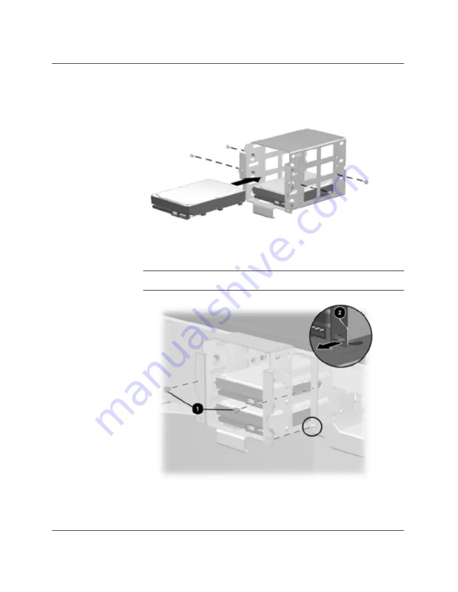
6.   To install an optional hard drive in the removable hard drive 

cage, see the following three illustrations. 


Installing a hard drive in bay 2 
 

CAUTION: Use only standard 6-32x3/16-inch guide screws. Longer screws 
can damage the internal components of the drive. 

Reinstalling the removable hard drive cage. 

2-32 

Compaq Evo Workstation W8000 Hardware Reference Guide


Summary of Contents for Evo W8000

Page 1: ...221474 002 September 2001 This guide is provided as a reference tool The topics contained herein describe specific features and will assist you with installing additional components such as hard drive...

Page 2: ...nstrued as constituting an additional warranty WARNING Text set off in this manner indicates that failure to follow directions could result in bodily harm or loss of life CAUTION Text set off in this...

Page 3: ...Location 1 10 2 Hardware Upgrades Installation Sequence 2 2 Removing the Workstation Access Panel 2 3 Removing the Front Bezel 2 4 Installing Additional Memory 2 6 Memory Expansion Board 2 7 RIMM Ins...

Page 4: ...rd Drive Installation Using the Cable Select Feature with Ultra ATA Devices B 1 Guidelines for Installing Ultra ATA Devices B 2 SCSI Devices B 3 Guidelines for Using SCSI Devices B 3 Guidelines for In...

Page 5: ...and Shipping Preparation Routine Computer Care F 1 CD ROM Drive Precautions F 2 Operation F 2 Cleaning F 2 Safety F 2 Shipping Preparation F 3 Index Compaq Evo Workstation W8000 Hardware Reference Gu...

Page 6: ...000 may vary depending on your model For a complete listing of the hardware and software installed in your workstation run the INSPECT utility described in the Troubleshooting Guide on the Reference L...

Page 7: ...ing 3 Hard drive activity light 9 CD ROM activity light 4 Power on light Diskette drive eject button 5 Headphone connector q Network link activity light 6 Two universal serial bus USB connectors w Mic...

Page 8: ...B 3 Keyboard connector 9 Parallel connector 4 68 pin SCSI connector Serial connector A 5 Two universal serial bus USB connectors q Ethernet connector 6 Line out audio connector w Video monitor connec...

Page 9: ...s Integrated PCI based audio Embedded Ethernet Network Interface Controller Dual Channel SCSI controller You may change the settings for these devices in Windows under Settings Control Panel System bo...

Page 10: ...te drive connector d Troubleshooting LEDs 9 Primary processor socket f 64 bit 66 MHz PCI sockets Primary Voltage Regulator Module VRM socket g Serial port connector q Processor fan connector h 32 bit...

Page 11: ...lly switch the audio signal from analog to digital See Solving Audio Problems in the Troubleshooting Guide on the Reference Library CD for instructions on how to manually switch the audio signal for y...

Page 12: ...o Key Used in combination with other keys to perform other functions see Windows Logo Key later in this section 3 Alt key Used in combination with another key its effect depends on the application sof...

Page 13: ...ss Software allows you to reprogram the Easy Access Buttons to reflect your personal preferences The buttons can be reprogrammed to any program or service of your choice or to any Web site URL Reprogr...

Page 14: ...he icons may require adjustment Windows Logo Key Use the Windows Logo Key in combination with other keys to perform certain functions available in the Windows operating systems Windows Logo Key F1 Dis...

Page 15: ...he software applications you are using Serial Number Location Each computer has a unique serial number located on the corner of the computer access panel and on the rear panel of the computer Keep thi...

Page 16: ...devices that were not included with your workstation Installation Sequence Follow this sequence of steps to ensure the proper installation of any optional equipment Before you begin observe the follo...

Page 17: ...l in this chapter 4 If you are installing or removing drives in the front bays see Removing the Front Bezel in this chapter 5 Install any optional equipment such as memory drives expansion boards a pr...

Page 18: ...operating system properly then turn off the workstation and any external devices Disconnect the power cord from the grounded AC outlet 2 To remove the workstation access panel refer to the following i...

Page 19: ...e Removing the Workstation Access Panel in this chapter 3 Remove the bezel a Push in on the two front bezel release latches 1 b Rotate the front bezel away from the chassis 2 to release it Releasing t...

Page 20: ...l B top and channel B bottom Each sub channel consists of two RIMM sockets Dual channels operate in unison not independently thus identical RIMMs must be installed in pairs across channels For example...

Page 21: ...hannel Location of RIMM sockets 1 RIMM Socket 1 Channel B Top 2 RIMM Socket 2 Channel A Top 3 RIMM Socket 3 Channel B Top 4 RIMM Socket 4 Channel A Top 5 RIMM Socket 5 Channel B Bottom 6 RIMM Socket 6...

Page 22: ...evices Disconnect the power cord from the grounded AC outlet 2 Remove the workstation access panel See Removing the Workstation Access Panel in this chapter 3 Remove the metal shipping bracket that ex...

Page 23: ...screw on the back of the metal slot cover that secures the memory expansion board to the memory expansion board socket Removing the torx screw on the back of the metal slot cover 2 8 Compaq Evo Workst...

Page 24: ...e memory expansion board from the memory expansion board socket 7 Carefully remove the memory expansion board from the memory expansion board socket 2 8 Locate the appropriate RIMM sockets and install...

Page 25: ...CC and non ECC memory in the same system Doing so will cause the system to blink the NUMLOCK LED on the keyboard continuously and if a speaker is installed in the system there will be a short beep fol...

Page 26: ...ber of Direct RDRAM devices on a RIMM cannot be changed Use 800 MHz RIMMs or future speeds only Your system will not boot if slower speed RIMMS i e 600 or 712 MHz are installed Do not mix RIMMs with d...

Page 27: ...npopulated RIMM sockets on channels being used Configuration 1 One Pair of RIMMs Location Contents RIMM Sockets 1 and 2 CRIMM RIMM Sockets 3 and 4 RIMM RIMM Sockets 5 and 6 Empty RIMM Sockets 7 and 8...

Page 28: ...IMM Sockets 3 and 4 RIMM RIMM Sockets 5 and 6 RIMM RIMM Sockets 7 and 8 RIMM Installing RIMMs WARNING To reduce the risk of personal injury when replacing or removing RIMMs allow the module being remo...

Page 29: ...es in this chapter CRIMMs must be installed in all unpopulated RIMM sockets on channels being used To install a RIMM 1 Shut down the operating system properly then turn off the workstation and any ext...

Page 30: ...ted and properly seated c Press inward on the two retainer latches 3 to secure the RIMM in the socket CAUTION Be sure to follow the configuration guidelines or your system will not function Installing...

Page 31: ...ansion Board To install a memory expansion board 1 Place the memory expansion board into the memory expansion board socket Locating the memory expansion board socket on the system board 2 16 Compaq Ev...

Page 32: ...expansion board press firmly on the board so that the whole connector seats properly in the memory expansion board socket After you install the memory expansion board make sure the board is engaged w...

Page 33: ...crew on the memory expansion board metal slot cover Securing the memory expansion board 3 Reassemble the workstation The workstation automatically recognizes the additional memory 2 18 Compaq Evo Work...

Page 34: ...orkstation supports up to seven drive bays See the following list for a description of the drive bay components Identifying drive bay components Drive bays 1 through 3 are located in the 3 5 inch remo...

Page 35: ...5 inch third height bay supports a 1 0 inch hard drive or a 1 6 inch hard drive 4 A 5 25 inch half height bay that supports 1 0 inch or 1 6 inch storage devices Either a CD ROM drive or DVD ROM drive...

Page 36: ...nal devices Disconnect the power cord from the grounded AC outlet 2 Remove the workstation access panel See Removing the Workstation Access Panel in this chapter 3 Remove the front bezel See Removing...

Page 37: ...e 1 Shut down the operating system properly then turn off the workstation and any external devices Disconnect the power cord from the grounded AC outlet 2 Remove the workstation access panel See Remov...

Page 38: ...of these bay locations To remove a cooling shield 1 Shut down the operating system properly then turn off the workstation and any external devices Disconnect the power cord from the grounded AC outlet...

Page 39: ...s Removing a cooling shield 5 Replace the cooling shield after the drive is installed in the bay To replace the cooling shield reverse the previous procedure 2 24 Compaq Evo Workstation W8000 Hardware...

Page 40: ...of 8 screws are standard 6 32 3 16 inch long screws and are for installing the hard drives The bottom group of 9 screws are metric M 3 5mm long and are for installing removable media storage devices...

Page 41: ...onents of the drive If you are installing an Ultra ATA device see Guidelines for Installing Ultra ATA Devices in Appendix B If you are installing a SCSI device see SCSI Devices in Appendix B To instal...

Page 42: ...n this chapter 5 To install a hard drive in bay 5 or bay 6 see the following four illustrations Installing a hard drive in the hard drive adapter Use only 3 16 inch long screws for both the adapter sc...

Page 43: ...Hardware Upgrades 2 28 Compaq Evo Workstation W8000 Hardware Reference Guide Installing a hard drive into the chassis Replacing the cooling shield...

Page 44: ...he cables to the appropriate system board connectors To locate the appropriate drive connectors see System Board Components in Chapter 1 7 Reassemble the workstation Reverse the previous procedures to...

Page 45: ...own the operating system properly then turn off the workstation and any external devices Disconnect the power cord from the grounded AC outlet 2 Remove the workstation access panel See Removing the Wo...

Page 46: ...o the drive cage See the following illustration for screw locations Locating the hard drive screw holes 1 1 0 inch drive 2 1 6 inch drive 3 1 0 inch drive 4 1 0 inch or 1 6 inch drive Compaq Evo Works...

Page 47: ...ee the following three illustrations Installing a hard drive in bay 2 CAUTION Use only standard 6 32x3 16 inch guide screws Longer screws can damage the internal components of the drive Reinstalling t...

Page 48: ...s to the appropriate system board connectors To locate the appropriate drive connectors see System Board Components in Chapter 1 8 Reassemble the workstation Reverse the previous procedure to remove a...

Page 49: ...x PCI sockets The following illustration identifies the physical locations of these sockets Identifying AGP and PCI sockets T h 1 One 1 5V AGP Pro socket 2 Four 32 bit 33 MHz PCI sockets primary bus 3...

Page 50: ...m the grounded AC outlet 2 Remove the workstation access panel See Removing the Workstation Access Panel in this chapter 3 Locate a vacant PCI or AGP socket depending on the type of board you are inst...

Page 51: ...guide AGP Pro Specifications allow an AGP expansion board with additional components or PCI expansion boards attached to occupy up to two adjacent PCI sockets on your workstation system board 6 Repla...

Page 52: ...horized reseller or service provider install the processor If you choose to install it yourself read all of the instructions carefully before you begin CAUTION Static electricity can damage the electr...

Page 53: ...affle at both ends b Rotate the end of the air baffle in an upward direction 1 c Pull the air baffle tab out of the front fan bracket 2 d Lift the air baffle out of the chassis Removing the air baffle...

Page 54: ...ly Use extreme care when placing the processor in the socket b Insert the new processor 2 and close the retention lever Ensure that the processor is locked into place and is not loose in the socket c...

Page 55: ...tall a Compaq approved VRM board when installing a second processor Using a VRM board that is incompatible with the primary VRM board may severely or permanently damage the system board b Install the...

Page 56: ...d CAUTION The air baffle is essential to proper cooling of the processors Without it the processors will slow down to avoid overheating Air flows across the processors from front to back The front fan...

Page 57: ...n access panel be sure to tighten all four thumbscrews A manual Hardware Abstraction Layer HAL upgrade is necessary when installing a second processor after the system has gone through the software un...

Page 58: ...stem board Have a Compaq authorized reseller or service provider install the processor If you choose to install it yourself read all of the instructions carefully before you begin CAUTION Static elect...

Page 59: ...ee the following sections Heatsink Cool Down Time Heatsink Warm Up Time 2 The heatsink must be separated from the processor 3 The processor must be released from the processor socket Heatsink Cool Dow...

Page 60: ...bly while the compound holding it to the processor is still pliable 1 Turn on the workstation and allow the operating system to boot 2 Shut down the operating system properly then turn off the worksta...

Page 61: ...that the heatsink is warm to the touch CAUTION Lifting the heatsink straight up while it is in a cold state can result in damage to the processor because it may prematurely pull the heatsink and proc...

Page 62: ...the heatsink straight up while it is in a cold state can result in damage to the processor because it may prematurely pull the heatsink and processor assembly out of the processor socket If this shou...

Page 63: ...tional Processor section in this chapter Disabling Onboard Devices Before installing an option you may have to disable another component such as Soundblaster NIC SCSI controller For example if you add...

Page 64: ...2 VAC 100 127 VAC 50 60 Hz 230 VAC 180 264 VAC 200 250 VAC 50 60 Hz Temperature Operating Shipping 50 to 95 F 4 to 140 F 10 to 35 C 15 to 60 C Humidity noncondensing Operating Nonoperating 20 to 80 10...

Page 65: ...80 conductor ATA cables See Guidelines for Installing Ultra ATA Devices in this appendix for an example of an Ultra ATA cable Compaq hard drives ship with jumpers preset to cable select mode therefore...

Page 66: ...drive connector 3 System board connector For optimum performance connect hard drives to the primary controller Connect expansion devices such as Ultra ATA CD ROM drives tape drives and diskette drive...

Page 67: ...mpaq recommends the following SCSI cable 53 inches maximum length twisted pair LVD cable with built in terminator maximum of 5 drives with a minimum drive spacing of 5 25 inches The SCSI controller re...

Page 68: ...devices The system accommodates a combination of internal and external SCSI devices such as hard drives tape drives and CD ROM drives Compaq does not recommend mixing different width SCSI devices on t...

Page 69: ...unique number See Guidelines for Using SCSI Devices in this appendix or refer to the documentation included with the device Determine if the device requires that termination be enabled or disabled Set...

Page 70: ...SCSI drive installed in the front drive bay area You can add additional high performance SCSI drives using the external SCSI connector located on the rear panel of the workstation Five device SCSI ca...

Page 71: ...n Immediately after exiting the logo screen press Ctrl A to access the SCSISelect utility A menu displays with the following options Configure View Host Adapter Settings SCSI Bus Interface Definitions...

Page 72: ...educe the risk of personal injury Do not attempt to recharge the battery Do not expose the battery to temperatures higher than 140 F 60 C Do not disassemble crush puncture short external contacts or d...

Page 73: ...tlet and remove the computer cover or access panel It may be necessary to remove an expansion card to gain access to the battery 2 Locate the battery and battery holder on the system board as shown in...

Page 74: ...lace any expansion boards you removed 6 Replace the computer cover or access panel 7 Plug in and turn on the computer 8 Reset the date and time your passwords and any special system setups using Compa...

Page 75: ...secure the workstation Because of differences between chassis the slot may be located in a different position than shown Securing the workstation 1 Separate the pieces of the security bracket by bend...

Page 76: ...system unit cover Next install the self tapping screw included in the cable lock kit 3 Cover the screw with the flat bracket 4 Install a lock not provided in the security bracket to control access to...

Page 77: ...age observe the following precautions Avoid hand contact by transporting and storing products in static safe containers Keep electrostatic sensitive parts in their containers until they arrive at stat...

Page 78: ...rovide proper ground wear the strap snugly against the skin Use heelstraps toestraps or bootstraps at standing workstations Wear the straps on both feet when standing on conductive floors or dissipati...

Page 79: ...cause this also restricts airflow Keep the computer away from excessive moisture direct sunlight and extremes of heat and cold For information about the recommended temperature and humidity ranges for...

Page 80: ...r before you turn off the power If you operate the unit immediately it may malfunction while reading Avoid placing the drive in a location that is subject to high humidity extreme temperatures mechani...

Page 81: ...he drive while in transit Do not use a diskette on which you have stored or plan to store data 4 Turn off the computer and external devices 5 Disconnect the power cord from the electrical outlet and t...

Page 82: ...42 2 45 VRM boards 2 40 CD ROM connector 1 5 CD ROM drives maintenance F 2 CMOS pushbutton switch 1 5 components drive bay 2 20 front panel 1 2 hot surfaces 2 2 2 43 installation sequence 2 2 configu...

Page 83: ...20 cage for 2 22 2 23 installing 2 26 SCSI B 3 Ultra ATA B 1 Hardware Abstraction Layer HAL 2 42 headphone connector 1 2 heatsink processor serparation 2 44 hood sensor connector 1 5 I I O connector 1...

Page 84: ...tion of 2 6 2 13 installation 2 15 location 2 7 memory configuration 2 13 personal injury warning 2 11 S safety warning 2 11 screws for drive installation 2 25 SCSI devices cables B 6 connector 1 5 co...

Reviews: