background image

6-7-06 - Fifth Proof

4-15

Routine Service and Maintenance

i. Reinstall the end cap (Item 4, Figure 4–19) so the dust ejector valve is down and secure 

the end cap with the two retaining clips. 

*In extremely dusty or dirty operating conditions, this service cycle may need to be 
shortened.

4. Replace fuel filter (Item 1, Figure 4–20). Shut off fuel at both of the fuel shut off valves 

(Item 1, Figure 4–21) by rotating the valve handle horizontally across the fuel line, shutting 
off the fuel. Remove the spring clamps (Item 2, Figure 4–20) from above and below the fuel 
filter and remove the fuel lines. Replace the fuel filter with a new filter.

Figure 4–20 Fuel Filter

Figure 4–21 Fuel Shut Off Valves

1

2

2

2047

1

Left Side of

E

ngine

1

Ri

g

h

t S

i

de of

E

ng

i

ne

2041

2033

Summary of Contents for BOXER 427 Operators

Page 1: ...Boxer 427 and Boxer 427W Operators Manual COMPACT TM COMPACT Part No 999 860 SN 992 and Higher BIG POWER IN ALL PLACES...

Page 2: ...6 7 06 Fifth Proof...

Page 3: ...or an authorized dealer of said defect The purchaser agrees to return the defective equipment or parts to Mertz Manufacturing LLC or to an authorized dealer facility freight prepaid within fifteen 15...

Page 4: ...facturing LLC or an authorized service facility or for any costs incurred with such removal or reinstallation CONSEQUENTIAL DAMAGES Notwithstanding any other provision of this agreement in no event sh...

Page 5: ...receipt of this form Not returning the form could result in your being denied some of your warranty entitlements To have Mertz Manufacturing LLC reset the warranty start date please complete the form...

Page 6: ...6 7 06 Fifth Proof iv Mertz Manufacturing LLC P O Box 150 Ponca City OK 74602 Affix Stamp Here...

Page 7: ...ecautions indicated whenever you see the Safety Alert symbol no matter which signal word appears next to the Safety Alert symbol INDICATES A HAZARDOUS SITUATION THAT IF NOT AVOIDED IS VERY LIKELY TO C...

Page 8: ...6 7 06 Fifth Proof vi...

Page 9: ...2 1 Rear View 2 2 Side View 2 3 Operating Controls 2 4 Safety Decals 2 5 Operating Controls Description 2 7 Section 3 Pre Start Inspection and Operation 3 1 Pre Start Inspection 3 1 Daily Service Che...

Page 10: ...Brake in Maintenance Procedures 4 9 Weekly Maintenance Procedures 4 12 Monthly Maintenance Procedures 4 14 Annual Maintenance Procedures 4 18 General Maintenance 4 20 Draining Fuel Tank Gasoline 4 20...

Page 11: ...nto the job site Resume work only when the operating area is clear Keep all non operating personnel away from the machine during operation Passengers must never be allowed to ride on the machine or an...

Page 12: ...erson enter the work area stop machine operation until the work area is clear Prior to unloading the unit and starting to work inspect the path you will travel and work site area for potential hazards...

Page 13: ...rior to resuming work Be alert to any unusual reaction to any of the controls If anything unusual is noticed shut the machine down and thoroughly inspect it to determine the cause of the problem Do no...

Page 14: ...ions and or work site hazards Be sure the area has adequate light and is well ventilated NEVER operate the machine inside a closed area Clean up any oil grease mud water or snow which might cause the...

Page 15: ...e is splashed into your eyes flush them immediately with clean water and seek medical attention If electrolyte is swallowed seek medical attention immediately If electrolyte is splashed onto exposed s...

Page 16: ...nnecting any hydraulic lines Hot hydraulic fluid can cause severe burns Hydraulic oil under pressure can penetrate body tissue causing serious injury and possible death When troubleshooting a hydrauli...

Page 17: ...ble to the machine before beginning the fueling process and keep the fuel nozzle in constant contact with the rim of the machines fuel tank To avoid static sparks when using a portable fuel container...

Page 18: ...6 7 06 Fifth Proof 1 8 Safety Precautions...

Page 19: ...Item No Description 1 Attachment mounting plate 2 Tilt cylinder 3 Auxiliary hydraulic quick connects 4 Boom 5 Fuel tank 6 Fuel filler cap 7 Operating controls 8 Hand grab rail 9 Manual holder 10 Lift...

Page 20: ...w Item No Description 1 Operator s platform 2 Engine oil dip stick fill tube 3 Engine 4 Engine choke knob 5 Air cleaner assembly 6 Manual holder 7 Fuel filler cap 8 Fuel tank 9 Ignition switch and key...

Page 21: ...of 2 3 Operating Controls Side View Item No Description 1 Rear drive wheel 2 Front drive wheel 3 Spark arrestor 4 Fuel tank 5 Attachment mounting plate 6 Boom 7 Air filter 8 Operator s platform 8 5 6...

Page 22: ...ge selector switch 2 Attachment tilt control 3 Attachment raise control 4 Engine throttle 5 Travel creep speed control 6 Fuel filler cap 7 Fuel tank 8 Service panel lock 9 Hand grip rail 10 Left trave...

Page 23: ...afety Decals Item No Description 1 Auxiliary Power Control Warning 2 Pinch Point Warning 3 Fuel Fill Warning 4 Boxer decal 5 Mertz corporate decal 6 Cylinder Lock Installation Warning 7 Brute Decal 8...

Page 24: ...ed Item No Description 1 Boxer Decal 2 Safety Instructions Decal 3 Operating Controls Information Plate 4 Engine Throttle Decal 5 Made In USA Decal 6 Auxiliary Power Control Warning 7 Pinch Point Warn...

Page 25: ...erse travel 5 Attachment Tilt Pushing the lever forwards tilts the attachment plate forwards lowering the attachment Pulling the lever backwards tilts the attachment plate backwards raising the attach...

Page 26: ...il Warning Light when the light turns on it indicates that the engine oil level is low Shut down engine immediately and add oil 10 Engine Throttle The engine throttle is located on the control panel c...

Page 27: ...Inspect the machine for any signs of damage or loose fasteners Check fluid levels and any signs of leaking fluids Do all Daily Service Checks Check machine controls to make sure that they automaticall...

Page 28: ...the engine oil filler tube Item 1 Figure 3 1 It is important to add the correct type of engine oil as stated in the engine manual NOTE Extremely dusty or dirty working conditions may require more freq...

Page 29: ...er pressure can penetrate body tissue causing serious injury and possible death When troubleshooting a hydraulic system for leaks always use cardboard or wood as a detector DO NOT USE YOUR BARE HANDS...

Page 30: ...lies to make sure that The tracks are in good condition and are not showing any signs of wear Track tension is properly set Track drive motors are not leaking oil or hydraulic fluid 8 Grease pivot sha...

Page 31: ...6 7 06 Fifth Proof 3 5 Pre Start Inspection and Operation Figure 3 4 Lubrication Points 2128...

Page 32: ...oader Arm Lift Cylinder Base Lubrication Point NOTE Extremely dusty or dirty working conditions may require more frequent service replacement Make sure to install the cylinder lock before performing a...

Page 33: ...y reinsert the safety lock pin Item 4 Figure 3 6 securing the cylinder lock in the support position NOTE Make sure that the safety lock pin goes behind the loader arm cylinder 7 Lower the loader arm a...

Page 34: ...rator must 1 Stand on the operator s platform Item 1 Figure 3 7 Figure 3 7 Operator s Platform and Safety Treadle 2 Pull the engine CHOKE knob Item 2 Figure 3 8 fully outwards 3 Move the throttle leve...

Page 35: ...the engine smoothes out As soon as the engine warms up and begins to run rough push the choke knob inwards to the normal operating position 7 Leave the throttle setting at about the halfway position...

Page 36: ...her be tilted or raised It is recommended to back the machine onto the transport trailer and position the machine so that the heaviest weight center of balance is towards the front hitch end of the tr...

Page 37: ...t to prevent possible carburetor flooding due to vibration Figure 3 11 Fuel Shut Off Valves NOTE Never tow or pull the machine Damage to the hydraulic motors could result If the machine is totally in...

Page 38: ...that this portion of the safety system is functioning properly The cogging condition is most likely to occur while operating in a reverse direction pulling a heavy load and during the first 50 hours o...

Page 39: ...ever The farther forward the right control is moved the faster the left turn will be made See Figure 3 15 2138 Figure 3 15 Left Hand Turn in Forward Right Turn During Reverse Travel Left Turn During R...

Page 40: ...alance Move the travel control levers in opposite directions to spin the machine on it axis To spin left move the right control lever forward while pulling the left control lever backwards to spin tur...

Page 41: ...p downwards securing the attachment to the machine If the lock pin does not drop into the locked position start the engine and either raise or lower the attachment slightly until the lock pins snap in...

Page 42: ...he female attachment mounting plate to remove any debris that might interfere with the attachment installation 2 Start the machines engine lower the loader arm and tilt the mounting plate forwards NOT...

Page 43: ...position See Figure 3 22 Figure 3 22 Attachment Installed 5 Shut the engine off 6 Rotate the attachment lock pins Item 1 Figure 3 22 and Item 1 Figure 3 23 into the locked position securing the attac...

Page 44: ...ttachment Installation of Hydraulically Powered Attachments There are many hydraulically powered attachments available that are very easy to install To install any of these attachments 1 Position the...

Page 45: ...t they are not damaged during the installation process Tuck the upper edge of the male mounting plate into the upper lip of the female attachment mounting plate Figure 3 26 Hydraulically Powered Attac...

Page 46: ...rward and backward to release any stored hydraulic pressure 10 Attach the hydraulic hoses to the quick connects See Figure 3 29 NOTE There are two hydraulic hoses that need to be connected The quick c...

Page 47: ...achments male coupling Item 3 Figure 3 30 into the female bulkhead quick connect coupling Item 1 Figure 3 30 on the machine and push until the connector locks into position e Repeat the above process...

Page 48: ...routed to keep them out of the way during operation and prevent them from being damaged Figure 3 31 Attachment Hydraulic Hose Routing 12 The attachment is now ready to use Before starting the engine m...

Page 49: ...gure 3 32 to the HIGH position before activating the AUXILIARY control lever If this switch is not set properly the auxiliary hydraulics and travel controls will not function properly 3 With your righ...

Page 50: ...of the hydraulic power to the attachment with no power going to the travel system 3 Hold the main travel control levers in either the fully forward or reverse position 4 Rotate the CREEP control lever...

Page 51: ...le quick connect Item 1 Figure 3 34 to align the notch on the collar with the lock button Item 2 Figure 3 34 4 Slide the collar backwards on the female quick connect Item 4 Figure 3 34 until it stops...

Page 52: ...6 7 06 Fifth Proof 3 26 Pre Start Inspection and Operation...

Page 53: ...conditions may require more frequent service replacement Under very wet and muddy conditions more frequent lubrication may be required Activity Daily 10 Hours New Machine 20 Hours Weekly 50 Hours Mon...

Page 54: ...engine is OFF a The Brute has a saddle tank Item 1 Figure 4 1 on each side of the machine Figure 4 1 Fuel Level Check b Each of the tanks has a gas gauge located in the filler cap Item 2 Figure 4 1 R...

Page 55: ...1 Figure 4 2 It is important to add the correct type of engine oil as stated in the engine manual NOTE Extremely dusty or dirty working conditions may require more frequent checking filling and or ch...

Page 56: ...hydraulic level dip stick d Unscrew and remove the hydraulic fluid dip stick Item 3 Figure 4 4 Make sure that the hydraulic fluid is at or slightly above the marker hole in the dip stick If you are c...

Page 57: ...ith hydraulic oil or any other fluids immediately seek treatment by a doctor trained in the treatment of penetrating fluid injuries a Fully raise the loader arm and secure the safety support b Open th...

Page 58: ...Hydraulic Lines and Fittings e If any signs of damage are visible do not operate the machine until repairs have been made and documented f When the inspection has been completed reinstall the upper in...

Page 59: ...Fifth Proof 4 7 Routine Service and Maintenance 7 Grease pivot shafts with proper type of grease There are 10 grease points on this machine see Figure 4 9 and Figure 4 10 Figure 4 9 Lubrication Point...

Page 60: ...shown on the side of the tire Make sure that the tires are not worn or damaged 9 Check for loose or missing fasteners a Inspect for any loose or missing bolts or fasteners b Tighten or replace any mis...

Page 61: ...e in Maintenance Procedures Do the following after the first 20 operating hours for a new machine only 1 Change engine oil see engine manual 2 Change engine oil filter which is located on the left sid...

Page 62: ...nd run the engine for about 30 seconds Using the hydraulic oil level dip stick Item 7 Figure 4 13 check the hydraulic oil level Add the appropriate hydraulic fluid as needed Figure 4 13 Hydraulic Oil...

Page 63: ...2 Figure 4 14 NOTE It may be necessary to rotate the adjustment nut slightly to align the adjustment nut keeper bolt f With the tracks still off the ground start the engine and rotate just the track...

Page 64: ...First 50 operating hours only then follow the normal service cycles 3 Check the in line fuel filter Item 1 Figure 4 15 for signs of water restrictions or contamination Replace as needed Figure 4 15 F...

Page 65: ...for damage to the spark plug cables Figure 4 17 Check Spark Plugs and Cables 6 Check the battery Item 1 Figure 4 18 and cable connections Items 2 and 3 Figure 4 18 for signs of leaking corrosion or da...

Page 66: ...fter the main element is removed check the condition of the inner element Item 2 Figure 4 19 It should be replaced whenever it appears dirty typically every other time the main element is replaced Cle...

Page 67: ...tened 4 Replace fuel filter Item 1 Figure 4 20 Shut off fuel at both of the fuel shut off valves Item 1 Figure 4 21 by rotating the valve handle horizontally across the fuel line shutting off the fuel...

Page 68: ...is being held securely to the machine Figure 4 22 Battery and Connections 6 Check for proper track tension if equipped a Raise the machine off the ground and support it using a device capable of safe...

Page 69: ...ate just the track being adjusted three or four times in both forward and reverse Shut off the engine after rotating the track g Remeasure the deflection dimension h Repeat the measurement and adjustm...

Page 70: ...Place a suitable sized container under the Brute b Remove the hydraulic tank drain plug Item 1 Figure 4 24 and drain all hydraulic fluid from the machine NOTE Make sure to inspect the O ring on the d...

Page 71: ...with the proper hydraulic fluid ISO 46 Premium hydraulic fluid or equivalent through the dip stick port Using the hydraulic fluid dipstick make sure that the hydraulic fluid is at or slightly above t...

Page 72: ...SHOULD ONLY BE DRAINED IN AN AREA THAT IS WELL VENTILATED 5 WIPE UP ANY GASOLINE THAT SPILLS 1 Park the machine on a level surface to make sure that the fuel tanks will be completely drained 2 Lower...

Page 73: ...the container selected to store the fuel can contain the capacity of both fuel tanks Make sure to dispose of the old gasoline in an appropriate manner NOTE Now is the best time to install a new fuel...

Page 74: ...6 7 06 Fifth Proof 4 22 Routine Service and Maintenance...

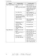
Page 75: ...not hold a charge replace the battery Electrical connections are corroded or loose Check electrical connections for good contact Remove cables from battery terminals and fully clean battery terminals...

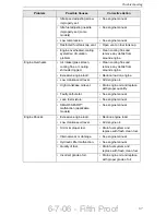
Page 76: ...iate storage container and dispose of bad fuel properly Refill fuel tanks with fresh clean fuel Replace fuel filter 30 Amp fuse blown Replace fuse Engine looses power Engine load is excessive Reduce g...

Page 77: ...nder seals are leaking Replace cylinder seals With the machines engine turned off boom drops downward quickly and then stops Cylinder seals are leaking Replace cylinder seals The machine does not trav...

Page 78: ...isconnected Check to make sure that both spark plug leads are securely attached to the spark plug and that they are not damaged Faulty spark plugs Replace spark plugs Faulty ignition module s Test and...

Page 79: ...Reverse position Move control lever to the Neutral position Dirt or water in the fuel system Drain fuel system and replace with fresh clean fuel Clogged fuel line Clean or replace fuel lines Loose or...

Page 80: ...it Tighten connections Engine overheated Clean cooling fins and remove any debris from around engine Faulty ignition module or incorrect air gap See engine manual Carburetor adjusted incorrectly See e...

Page 81: ...ive engine load Reduce load on engine Low crankcase oil level Add engine oil High crankcase oil level Drain engine oil and replace with proper quantity Faulty carburetor See engine manual Lean fuel mi...

Page 82: ...around engine Faulty spark plugs Replace spark plugs Low compression See engine manual Exhaust restriction Clean spark arrestor See engine manual SMART SPARK malfunction applicable models See engine...

Page 83: ...torqued fasteners See engine manual Piston blow by or leaky valves See engine manual Restricted exhaust Clean spark arrestor See engine manual Engine Power Gasoline 27 HP Engine Manufacturer Kohler En...

Page 84: ...Width 43 5 Weight without bucket 2 250 LBS Tip Capacity 1 800 LBS Dump Angle 34 Dump height 56 Hinge pin height fully raised 70 Travel speed 3 5 MPH Fuel tank capacity 10 GAL Overall Operating Height...

Page 85: ...6 7 06 Fifth Proof...

Page 86: ...6 7 06 Fifth Proof Compact Power Inc P O Box 40 Fort Mill SC 29716 Phone 800 476 9673 Fax 803 548 2762 Web Site http www cpiequipment com Part No 999 860...

Reviews: