INS_FVT/FVR8014_REV–
05/10/10
PAGE 3
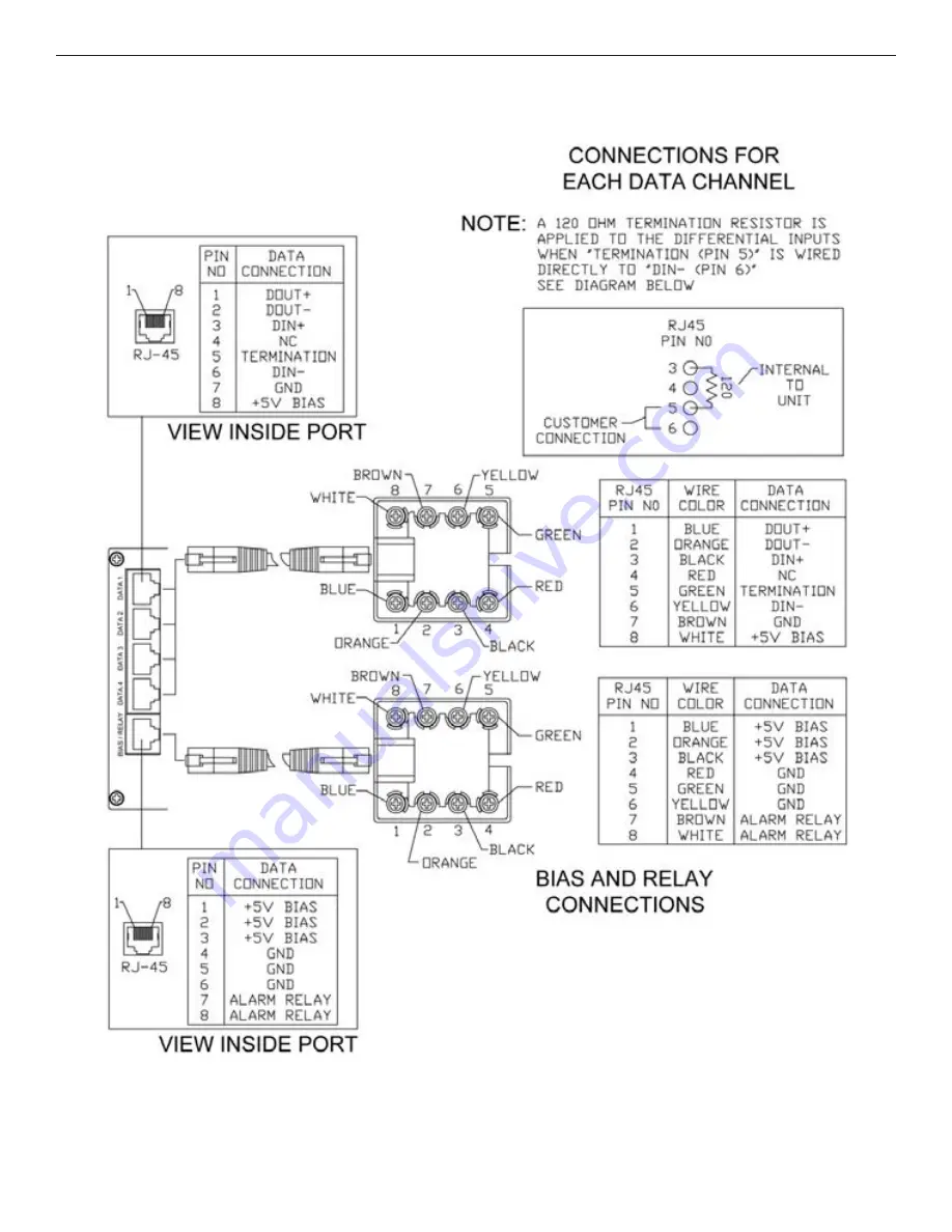
FIGURE 4 – RJ45 BREAK-OUT
5 pc. Factory Supplied
INSTALLATION AND OPERATION MANUAL
FVT/FVR8014
TECH SUPPORT: 1.888.678.9427
Page 1: ...icates that the optical communication link is operating properly The Relay is CLOSED when the optical communication is good The Data Channels are labeled A B C and D Each data channel is configured fo...
Page 2: ...H WHITE STRIPE FIGURE 2 FVT8014 TRANSMITTER FIGURE 1 FVT FVR8014 TRANSMITTER AND RECEIVER FIGURE 3 FVR8014 RECEIVER INSTALLATION AND OPERATION MANUAL FVT FVR8014 NOTE Remove Electrical Connector for R...
Page 3: ...INS_FVT FVR8014_REV 05 10 10 PAGE 3 FIGURE 4 RJ45 BREAK OUT 5 pc Factory Supplied INSTALLATION AND OPERATION MANUAL FVT FVR8014 TECH SUPPORT 1 888 678 9427...
Page 4: ...s on the front panel of the unit FIGURE 6 SWITCH SETTINGS RS232 1 NC 2 Out 3 Ground 4 NC 5 NC 6 IN 7 NC 8 NC RS485 2W SENSORNET 1 NC 2 NC 3 IN 4 NC 5 NC 6 IN 7 NC 8 NC RS422 RS485 4W Manchester Bi Pha...
Page 5: ...DIN DIN Data Out A Data Out B Data In A Data In B Data In A Data In B Data Out A Data Out B DIN DIN DOUT DOUT DOUT DOUT DIN DIN Data Out Data Out Data In Data In Data In Data In Data Out Data Out FIGU...
Page 6: ...riented right side up and slide it into the card guides in the rack until the edge connector at the back of the card seats in the corresponding slot in the rack s connector panel Seating may require t...