CommScope SYSTIMAX 360 iPatch PATCHMAX Instruction Sheet Download Page 6

Instruction Sheet:

 SYSTIMAX 360™ iPatch

® 

PATCHMAX

®

  Modular Panel

6

© 2010 CommScope, Inc. All rights reserved.

Installing the Patch Cord Management 
and Front Bezel

To complete the installation of the SYSTIMAX 360

™ 

iPatch

®


PATCHMAX

®

 Modular Panel, install the patch cord management 

and bezel on the front of the panel.

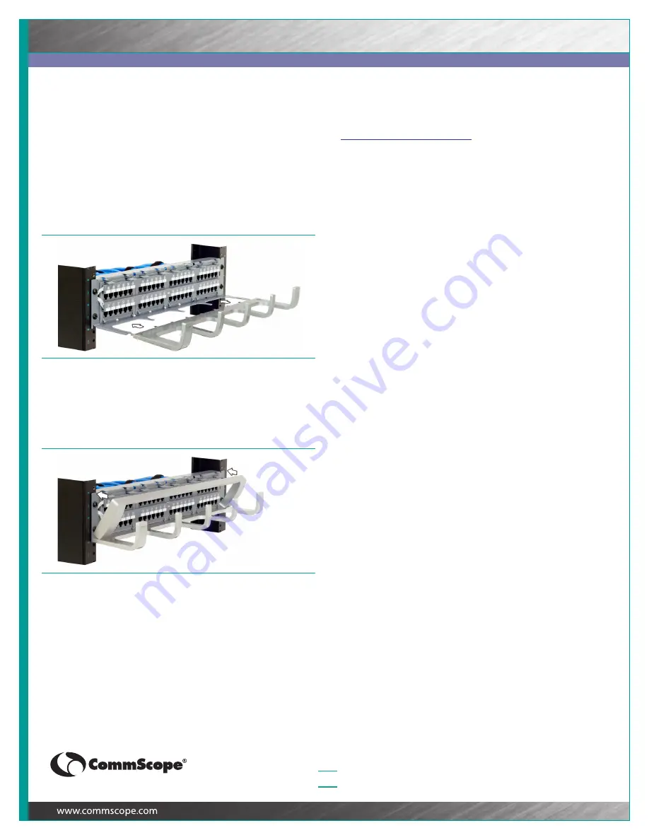
To install the patch cord management and front bezel:

1

Align the patch cord management as shown in Figure 14 and 
slide it onto the mounting arms until fully seated.

2

Position the front bezel at an angle as shown in Figure 15 and 
insert the 2 bottom retention tabs into the slots on the patch cord 
management.

3

Pivot the top of the bezel towards the panel until the 3 tabs on 
the top of the bezel snap into the panel (Figure 15).

4

Restore power to the rack’s Panel Manager.

How To Contact Us

To find out more about SYSTIMAX

®

 Solutions, visit us on the web at 

www.commscope.com/systimax

For technical assistance regarding SYSTIMAX products:

ƒ

Within the United States, contact your local account 
representative or CommScope Technical Support at 
1-800-344-0223.

ƒ

From outside the United States, contact your local account 
representative or Authorized BusinessPartner.

Figure 14 Installing the Patch Cord Management

Figure 15 Installing the Front Bezel

Summary of Contents for SYSTIMAX 360 iPatch PATCHMAX

Page 1: ... installed GS3 DM or GS5 DM 6 pack or 12 pack modules 4 cabling labels for B wiring 4 or 8 iPatch sensor overlay 1 or 2 panel bus jumper 1 or 2 Patch cord management Front bezel Cable support bar Cable troughs 4 Cable straps 4 12 24 x 1 2 inch screws 4 for mounting the panel in a 19 inch 482 6 mm rack Cabling labels for A wiring 4 or 8 Termination Managers 28 or 56 and instruction sheet Related Co...

Page 2: ... that the labels are oriented with the right side up Figure 1 3 Install the panel on the rack using the 4 screws provided Figure 2 Be careful not to pinch the panel bus jumper s between the panel and rack 4 Connect the panel bus jumper a Remove the adhesive backing from the cable retainers on the panel bus jumper b Connect the panel bus connector on the jumper to the nearest connector on the panel...

Page 3: ...e rear cable support following the instructions in Installing the Rear Cable Support Optional on page 5 Cabling from the Front To cable modules from the front of the panel Important Power must be removed from the rack s Panel Manager when cabling modules for the panel 1 Install the rear cable support following the instructions in Installing the Rear Cable Support Optional on page 5 Note Loosely se...

Page 4: ...backwards position the lower edge of the module into the panel opening so the small tabs hook onto the edge of the opening Figure 8 Then gently press the top of the module until the module snaps into place 5 Pull the cables through the panel opening where the module will be installed and mark the cables for termination leaving an adequate length of cables to reach the module Make sure that the cab...

Page 5: ... the overlay on the panel so the hooks on the back of the overlay fit into the front of the panel c Slide the overlay to the left so the hooks engage with the panel and the buttons align with the ports Important For 48 port panels reinstall both iPatch sensor overlays Installing the Rear Cable Support Optional The SYSTIMAX 360 iPatch PATCHMAX Modular Panel includes rear cable management When cabli...

Page 6: ...Figure 15 and insert the 2 bottom retention tabs into the slots on the patch cord management 3 Pivot the top of the bezel towards the panel until the 3 tabs on the top of the bezel snap into the panel Figure 15 4 Restore power to the rack s Panel Manager How To Contact Us To find out more about SYSTIMAX Solutions visit us on the web at www commscope com systimax For technical assistance regarding ...

Reviews: