


Earth Grounding the AP
CAUTION! Make sure that earth grounding is available and that it meets
local and national electrical codes. For additional lightning protection,
use lightning rods and lightning arrestors.
NOTE: The color coding of ground wires varies by region. Before
completing this step, check your local wiring standards for guidance.
Using the factory-supplied ground wire and ground screw and washer set,
connect a good earth ground to the AP chassis ground point. Tighten the
screw to 3.0 N.m. (27 in-lbs).
CAUTION! The Q950 AP includes one 12-mm stainless steel M6x1 earth
ground screw with split lock and flat washers. Make sure that any
replacement screw is no longer than 12 mm. If a screw is longer than 12
mm, it can damage the AP chassis.
FIGURE 11 Connecting a Good Earth Ground to the AP
1. Earth ground screw
Installing the Security Cable
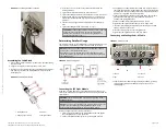
1. Thread the security cable through the mounting bracket and through
the eye on the cable itself.
2. Attach the safety cable to the AP and tighten the screw to 3.0 N.m.
(27 in-lbs).
FIGURE 12 Attaching the Security Cable
1. Mounting bracket
2. Eye on the cable
3. Safety cable attached to
the AP
Deploying Cold Shrink
Use the cold shrink kit to seal connectors.
NOTE: Cold shrink is not part of the package contents. You can order
the Cold Shrink Kit from CommScope (Part Number: PS-CWRN).
NOTE: N-Type connectors shown are representative examples.
NOTE: Weather sealing with cold shrink or tape on both ends of the
cable is recommended.
1. Ensure the AP is disconnected from the power source to avoid
electrocution or equipment damage.
2. Clean all traces of dust, grease, and oil from your hands.
3. Clean off any traces of dust, grease, and oil from the N-Type bulkhead
connector external threads.
4. Make sure that the connectors are dry before continuing.
5. Preconditioning: Hold the shrink sleeve at a comfortable angle and
pull the plastic tab until the front end of the plastic is removed and is
even with the shrink sleeve, as shown in the following figures.
FIGURE 13 Pulling the Plastic Tab
FIGURE 14 Evening the Plastic Tab with the Shrink Sleeve
6. Preconditioning: Slide the shrink sleeve over the RF cable connector
assembly making sure the plastic tab is oriented away from the RF
cable.
Copyright
©
2020 CommScope, Inc. All rights reserved.
Page 4 of 5
Published September 2020, Part Number 800-72458-001 Rev A
Times
tamp: 2020 Oct
ober 7 6:04 | Codes
tamp: 2020 Ma
y 08 11:00 UT
C (O
T: 2.5.4)—c
ommsc
ope log
o o
verride added