


Local Area Connection > Properties > Internet Protocol Version 4
(TCP/IPv4) > Properties
The Internet Protocol Version 4 (TCP/IPv4) Properties dialog box
appears.
IMPORTANT-QSG: Write down all of the currently active settings
so you can restore your computer to its current configuration later
(when this process is complete).
3. Select Use the following IP address (if it is not already selected) and
then make the following entries:
• IP address: 192.168.0.22 (or any available address in the
192.168.0.x network, except 192.168.0.1)
• Subnet mask: 255.255.255.0
• Default gateway: 192.168.0.1
Leave the DNS server fields empty.
4. Click OK to save your changes. Your changes are put into effect
immediately.
Step 4: Logging Into the AP
1. As specified in Step 3, the admin PC should be directly connected to
the AP through one of the Ethernet ports and powered on, ready for
setup.
2. On your admin PC, open a web browser window.
3. In the browser, enter the following URL in the browser navigation bar:
https://192.168.0.1
4. Press Enter to initiate the connection. When the security alert dialog
box appears, click OK/Yes to proceed.
5. When the Ruckus Admin login page appears, enter the following:
• Username: super
• Password: sp-admin
6. Click Login. On your first login, you will be prompted to change the
default password.
7. When the Change Password dialog box displays, enter the following:
• New Password: Enter a new password.
• Confirm Password: Re-enter the new password.
8. Click Submit.
9. Log in using the new password.
Step 5: Customizing the Wireless Settings
TABLE 2 Default AP Settings (for your reference)
Network Names (SSIDs)
Wireless1—Wireless8 (2.4GHz
radio)
Wireless9—Wireless16 (5GHz
radio)
Security (Encryption method)
Disabled for each wireless
interface
Default Management IP Address 192.168.0.1
1. On the web interface menu, click Configuration > Radio 2.4G or
Configuration > Radio 5G. TheConfigure > Wireless > Common page
appears.
2. Verify that the following options are active:
Channel : SmartSelect
Country Code: If you are not located in the United States of America,
select your current country.
3. Click Update Settings if you made any changes.
4. Click any of the Wireless # (Wireless LAN Number) tabs at the top of
the page.
5. In Wireless Availability, click Enabled.
6. Delete the text in the SSID field, then type a name for your network
that will help your users identify this AP in their wireless network
application.
7. Click Update Settings to save your changes.
8. Repeat for each Wireless # (Wireless LAN Number) interface that you
want to enable.
9. Click Logout to exit the web interface.
10. When the Ruckus Admin login page reappears, you can exit your
browser.
11. Disconnect the AP from the computer and from the power source,
and then restore your computer to its original network connection
configuration settings.
Step 6: Placing the AP in Your Site
1. Move the AP to its permanent location (accessible to both power and
network connections). Refer to the Mounting Instructions section for
physical installation.
2. Use an Ethernet cable to connect the 5G ETH PoE port to an
appropriate device:
• The ISP’s or carrier’s network device.
• An Ethernet switch that is connected to the ISP’s or carrier’s
network device.
3. Connect the AP power adapter (or PoE power supply) to the AP, and
then to a convenient power source.
NOTE: If you will be using PoE, then you will need a Cat 5e (or
better) Ethernet cable to connect the AP to the PoE switch or PoE
injector.
NOTE: The power draw will identify as a Class 4 device with a max
draw of 25.5W if it is powered by an 802.3at PoE switch.
NOTE: The R850 supports 802.3at and 802.3at+ PoE modes only,
and does not support 802.3af PoE mode.
4. Verify that the 5Gbps port LED is lit.
After a short pause to re-establish the Internet connection, you can
test the AP.
Step 7: Verifying the Installation
1. Using any wireless-enabled computer or mobile device, search for
and select the wireless network you previously configured.
2. When connected, open a browser and connect to any public website.
Congratulations! Your wireless network is active and ready for use.
Mounting Instructions
Mounting on a Drop-Ceiling T-Bar
The factory-supplied T-bar mounting assembly kit allows you to attach the
AP to recessed and flush drop-ceiling T-bars.
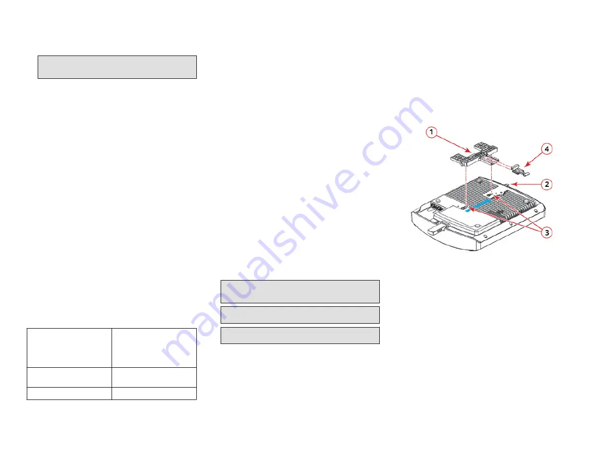
1. Position the studs on the bottom of the T-bar bracket (1 in the
following Figure) in the keyholes on the AP enclosure.
2. Slide the T-bar bracket away from the Ethernet ports on the bottom
of the AP until the AP retainer tab (2) snaps into place, trapping the T-
bar bracket studs in the keyholes (3).
FIGURE 3 Attaching the T-bar bracket to the AP
3. Insert the locking tab (4) so it is in the first position on the T-bar
bracket (1).
4. Gently push the ceiling tiles, if present, up and out of the way.
5. Position the T-bar bracket so its two clasps grip one edge of the T-bar
(1 in the Figure below). Make sure that both clasps are gripping the T-
bar.
6. Hold the AP in place and gently push the locking tab (2) until its clasp
grips the other edge of the T-bar. Make sure that all three clasps are
gripping the T-bar.
Copyright
©
2020 CommScope, Inc. All rights reserved.
Page 2 of 4
Published April 2020, Part Number 800-72487-001 Rev B


