


TECP-90-702 • Issue 4 • April 2017
Page 21
© 2017, ADC Telecommunications, Inc.
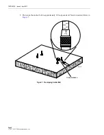
9. Install the hole cover in the location shown in
.
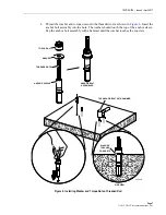
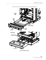
10. Re-install the front and rear troughs, as shown in
11. Re-install FOTSP front and rear guard boxes (reverse of steps 3 and 4, and reverse of what
and
).
5
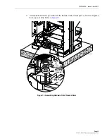
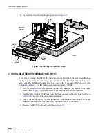
GROUNDING THE FRAME
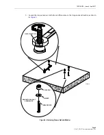
Standard grounding is accomplished by connecting a compression lug to a grounding point on
the top member of the frame, as shown in
. Any 2-hole location with the correct hole
spacing may be used. Use a 2-hole #10 compression lug with 3/4 inch hole (1.905 cm) spacing.
Scrape the paint to expose bare metal and apply deoxidant in the grounding location. For a
grounding wire, use only 6 AWG or thicker copper wire. Follow local practice to connect the
ground wire to office ground.
Figure 22. Grounding the Frame
6
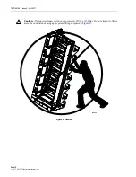
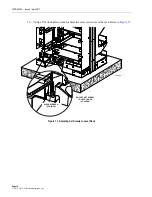
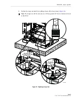
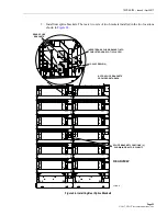
SECURING TWO FRAMES TOGETHER
When a NG4access frame is installed adjacent to an existing NG4access frame, the frames must
be secured together. This is done using the following items shipped with the frame:
• Junction plates (6);
TO OFFICE
GROUND
GROUND
LUG
25082-A