ADCP-96-167 • Issue 5 • July 2016
Page 30
© 2016, CommScope, Inc.
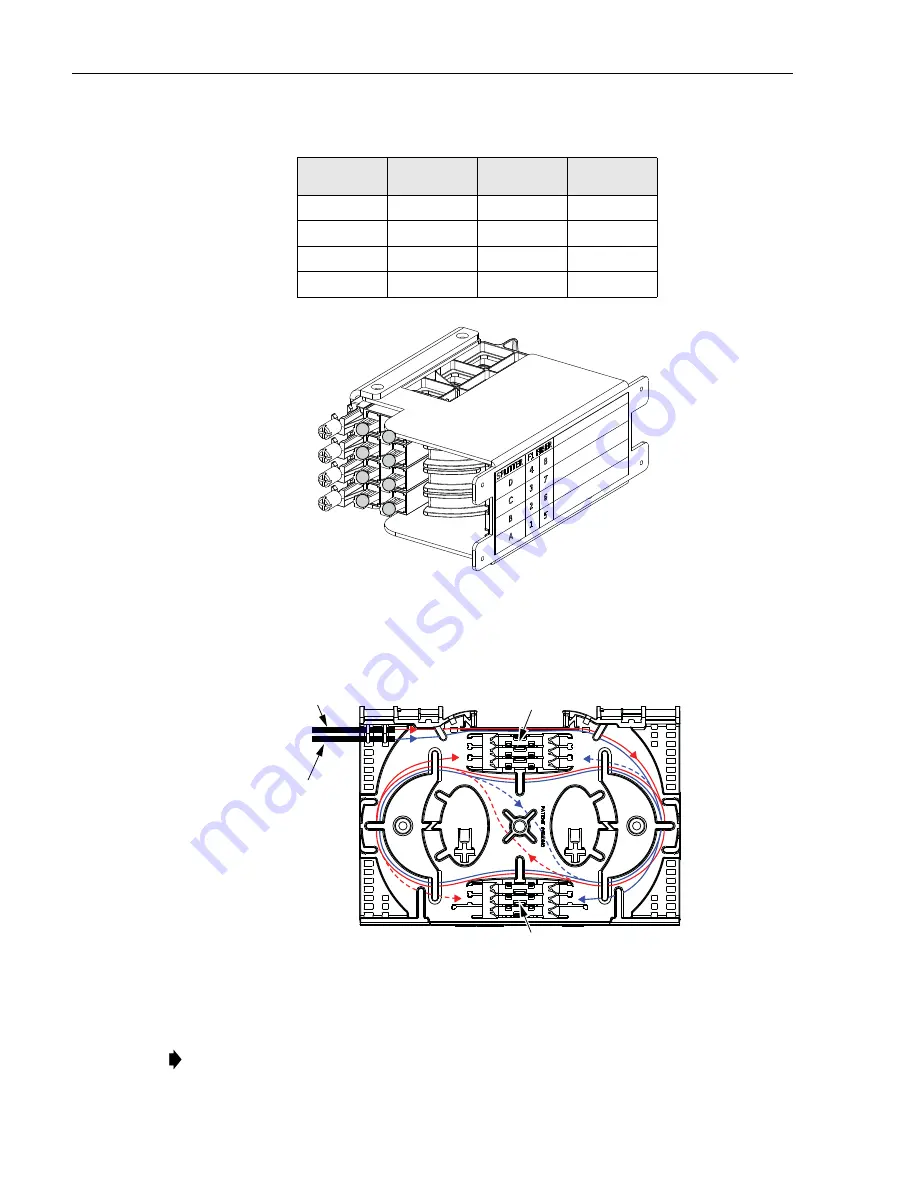
Figure 21. Splitter Input Port Designations
3. Adjust and route the individual fibers within the splice tray as each splice is
completed as shown in
Figure 22. Splicing Stranded Feeder Cable
4. Mount the splice chips within the splice tray as shown in
Table 3. Splitter Input Fiber Designations
SPLITTER
POSITION
FIBER COLOR
INPUT 1
SPLITTER
POSITION
FIBER COLOR
INPUT 2
A1
Blue
A5
Slate
B2
Orange
B6
White
C3
Green
C7
Red
D4
Brown
D8
Black
Note:
Two splice chips may be mounted in each splice holder.
A
B
C
D
24490-A
1
2
3
4
5
6
7
8
SPLICE HOLDERS (6)
SPLICE HOLDERS (6)
SPLITTER INPUT FIBERS
FEEDER CABLE
FIBERS
24348-B
DASHED LINES SHOW
REVERSE ROUTING TO
ALTERNATE HOLDER


