


CommScope Era
™
Fiber Low Power Carrier Access Point Installation Guide
M0201ANC_uc
Page 60
© June 2019 CommScope, Inc.
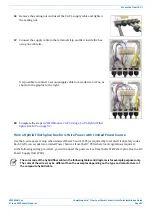
Connect the Cables to the Fiber CAP L
Do the following to connect a Fiber CAP L to a passive RF antenna.
1
Connect the CAP L ANT 1 or ANT 2 connector to a passive RF antenna.
a
Locate the 50
coaxial cables obtained for this installation; see
"Obtain the Required Materials” on
b
Install the passive antennas per the manufacturer’s installation instructions. For MIMO CAP L, if
connecting both ANT connectors, you will connect the CAP L to either two separate external passive
antennas or to two ports on a cross-polarized dual antenna. Each connector supports two RF bands
(see
).
Table 12.
Mapping Frequency Bands to Antennas
ID Number
Ant 1
Ant 2
17E/17E/23/23
7770203-000x
17E/23
17E/23
1 8 /2 1 /2 6 /2 6
7770209-000x
18/26
21/26
17E/17E/19/19
7770356-000x
17E/19
17E/19
9 /1 8 /1 8 /2 1
7776595-000x
9 / 1 8
18/21
7/80-85/17E/19
7776596-000x
7 / 8 0- 8 5
17E/19
17E/19/23/25TDD 7776597-000x 23/25TDD 17E/19
9 /1 8 /2 1 /2 6
7776598-000x
9 / 1 8
21/26
8 /9 /1 8 /2 1
7776641-000x
8 / 9
18/21
8 /1 8 /2 1 /2 6
7776643-000x
8 / 1 8
21/26
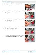
c
Remove the plastic-protective cap from the 4.3-10 connectors.
d
Remove the IP67/EMI blank plug from the ANT 1/2 connector.
e
Connect the passive multi-band antenna to the ANT 1 or ANT 2 connector using coaxial cable with the
least amount of loss possible.
•
If the 50
coaxial cable has a push-pull connector, make sure the cable is seated firmly in the
ANT 1 or ANT 2 connector.
•
If the 50
coaxial cable has a threaded connector, torque the connector 5 N-m (3.69 ft-lb). Do not
over-tighten the connector.
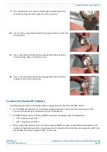
f
Connect the other end of the 50
coaxial cable to the passive antenna installed in
2
to connect a 50
coaxial cable to the other ANT connector.
Connect the Fiber CAP L to a Classic CAN or TEN
The following steps are applicable to a singular Fiber CAP L, or to the Primary CAP L in a cascade.
1
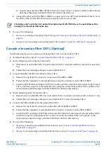
Connect the CAP L Optical Port 1 as appropriate for this installation.
a
Remove the dust cap from the CAP L Optical Port 1 connector and the connectors on the SMF or MMF.
b
Follow the local cleaning technique to clean Optical Port 1.
c
Clean the connectors on the SMF or MMF following the fiber supplier’s recommendations.
d
Install the SFP+ connector and Optical OCTIS Kit on the end of the SMF or MMF that will connect to
the CAP L.
i
Follow the limitations per the maximum range described in


