


20
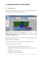
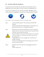
5.4
Connect with the Hardware
The real robot can be controlled in the same way as the simulated one, only the
hardware has to be connected before: connect, reset errors and enable motors.
Prerequisites are that the robot is connected via the USB-CAN adapter and the
robots supply is running (plugged in, switched on and emergency button released).
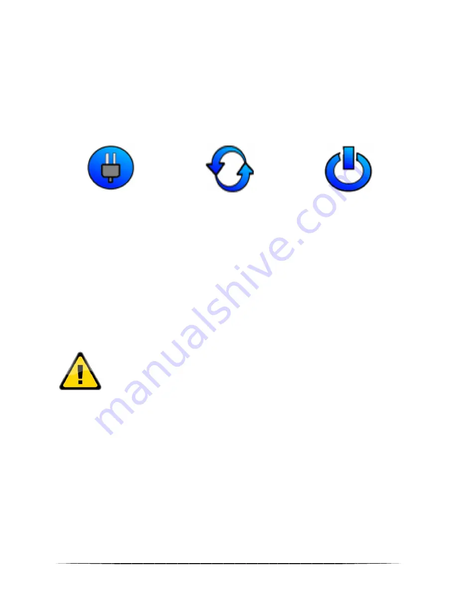
Pic. 11: Buttons to connect to the hardware, reset the errors and enable the motors
Step 1:
Connect with the hardware. This step initializes the USB-CAN
interface.
The LED on the left side of CPRog changes color from grey to red.
Below the LED several error messages are displayed.
Step 2:
Reset the errors. This button resets the error memory of the joint
module controller in the robot. The joint values are copied from the
real robot to the simulation environment.
The 3D visualization of the robot has to match the current pose
of the real robot now. This has to be verified every time the
errors are reset!
The LED stays red. The error messages clear, only “Motors not
enabled“ remaining.
If further error messages remain visible try again and see section
9.3 for possible approaches.
Step 3:
Enable the motors. Now the robot can be jogged as described
above.
The LED is green now.
Summary of Contents for Robot arm mower 4
Page 1: ...1 Bedienungsanleitung Mover4...
Page 2: ...2...


