


Revision A1.1
The design and specifications are subject to change without notice for improvement
Page 2 of 16
www.CommFront.com
■
INTRODUCTION
The USB-232-1 is a port-powered USB to RS-232 converter that can be used to convert any standard
USB port (USB 2.0 - backward compatible) into a RS-232C port. The unit uses the latest FTDI chipset
and is fully compatible with Windows 7/Vista/XP/Server2008/Server2003/2000/98 (32-bit), Windows
7/Vista/XP/Server2008/Server2003 (64-bit), Win CE, Mac, and Linux.
Note: the latest drivers (chipset FT232B) are available at
http://www.ftdichip.com/Drivers/VCP.htm
.
■
FEATURES
•
Adds one RS-232 port to your USB port.
•
RS-232 data & signals: TX, RX, RTS, CTS, DTR, DSR, DCD, RI, and GND.
•
Supports Windows 7/Vista/XP/Server2008/Server2003/2000/98 (32-bit), Windows 7/Vista/XP/
Server2008/Server2003 (64-bit), Win CE, Mac, and Linux.
•
Supports remote wakeup and power management.
•
Port-powered, no external power required.
•
Plug and play (hot-pluggable, data format auto-sensing and self-adjusting).
•
No IRQs required, no IRQ conflicts.
•
Surface Mount Technology manufactured to RoHS and ISO-9001 standards.
•
Safety: Strictly certified by SGS / 5-year manufacturer’s warranty.
■
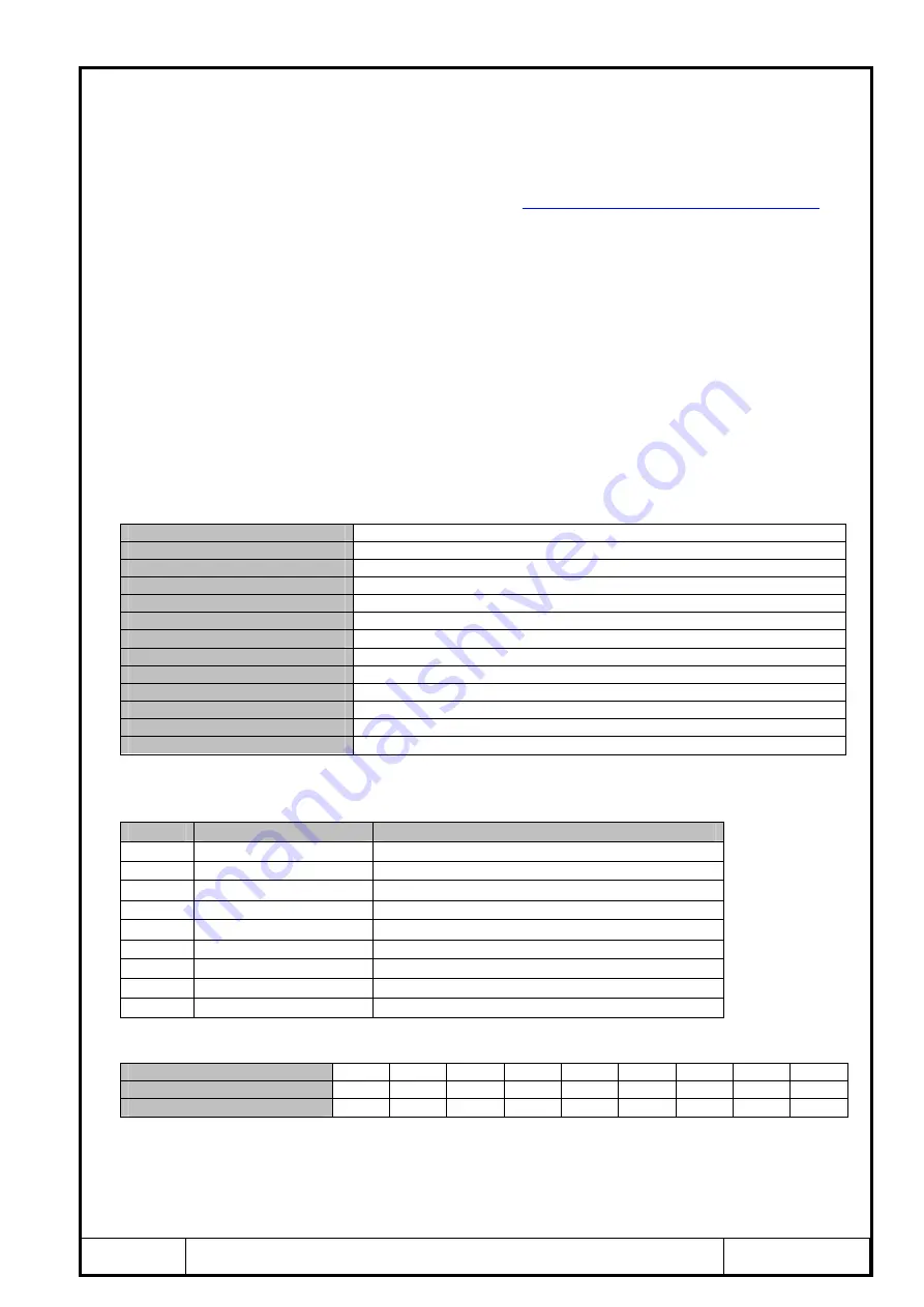
SPECIFICATIONS
Compatibility:
USB 2.0 (backward compatible) and EIA/TIA RS-232C standards
Power Source:
From USB port
Current Consumption:
Under 100mA
Output Power on Pin 3 (TX):
About -9VDC
RS-232 Data Rate:
300 to 128,000bps (auto-sensing and self-adjusting)
Distance:
USB side: 10ft (3m); RS-232 side: 16ft (5m)
Connectors:
USB side: Type A Female; RS-232 side: DB-9 Male
LEDs:
TX, RX and Power
Dimensions (H x W x D):
0.6 x 1.4 x 2.2 in (15 x 35 x 55 mm) (excluding cable)
Cable Length:
3.3 ft (1 m)
Weight:
2.6 oz (73 g)
Operating Temperature:
32ºF to 95ºF (0ºC to 35ºC)
Operating Humidity:
Up to 90% RH (no condensation)
■
PIN ASSIGNMENT
RS-232 Side (DB-9 Male Connector / DTE):
Pin
Function
Description
1
DCD
Data Carrier Detect
2
RX
Receive Data
3
TX
Transmit Data
4
DTR
Data Terminal Ready
5
GND
Ground (Signal)
6
DSR
Data Set Ready
7
RTS
Request to Send
8
CTS
Clear to Send
9
RI
Ring Indicator
■
DB-9
DB-25 CONVERSION TABLE (DTE)
DB-9 Pin Assignment:
1
2
3
4
5
6
7
8
9
DB-25 Pin Assignment:
8
3
2
20
7
6
4
5
22
Function:
DCD
RX
TX
DTR
GND
DSR
RTS
CTS
RI
■
DRIVER INSTALLATION – QUICK GUIDE
•
Drivers are included on the CD supplied with the converter; insert the CD into the
drive.
•
Connect the USB-232-1 to an available USB port, and the “Found New Hardware


