LP-17A User’s Manual
-27-
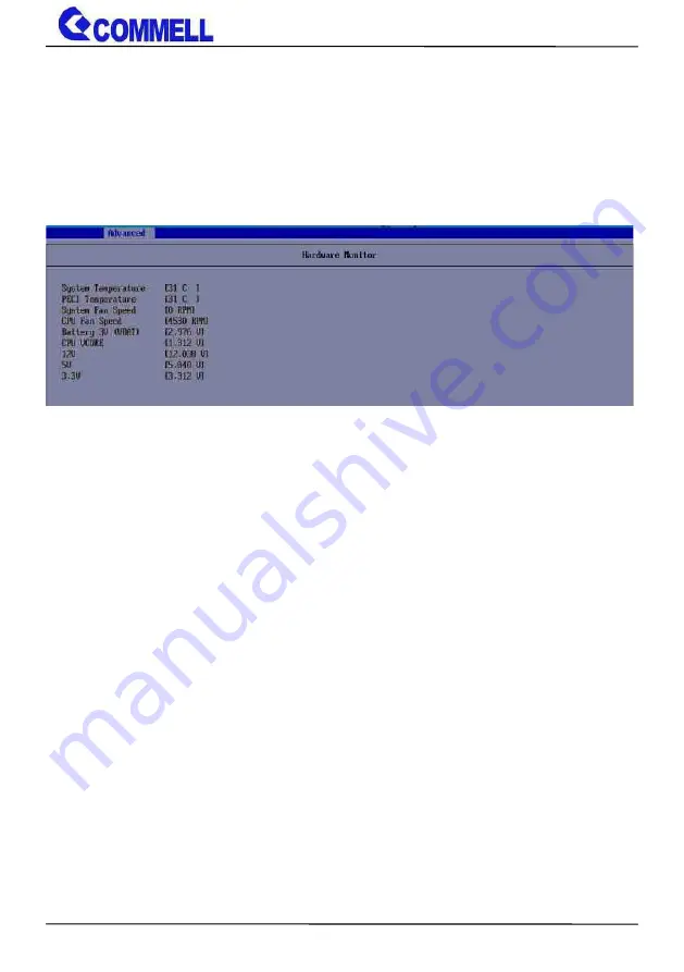
Appendix D <Hardware Monitor>
Find the setting from
Advanced-> Motherboard Advanced menu-> Super IO configuration->
Hardware Monitor
Page 1: ...LP 17A Pico ITX Motherboard User s Manual Edition 1 1 2022 10 14 ...
Page 2: ...ment are property of their respective owners Disclaimer The company shall not be liable for any incidental or consequential damages resulting from the performance or use of this product The company does not issue a warranty of any kind express or implied including without limitation implied warranties of merchantability or fitness for a particular purpose The company has the right to revise the ma...
Page 3: ...ing Cooler Fan 1 xUSB2 0 cable OALUSBA 3 1040173 1 x Audio cable OALPJ HDUNB 1040123 _ 1 xDC Input Power Cable OALDC B 1040513 1 x Driver CD Including User s Manual 1 x COM Cable OALES BKU1 H14NB 1040378 ADP 3460SMB DisplayPort to LVDS module Including CN_EDP Cable 1 x SATA SATA Power Cable OALSATA22B PM10SL10 1040671 OALSATA22B PM5S10 1040460 OALDC B 1040513 ...
Page 4: ...ry 12 2 4 I O interface 13 2 4 1 Serial ATA interface 13 2 4 2 Ethernet interface 14 2 4 3 Display interface 14 2 4 4 Serial Port interface 16 2 4 5 USB interface 17 2 4 6 Audio interface 18 2 4 7 Type C 18 2 4 8 Expansion slot 19 2 4 8 Front panel switch and indicator 20 2 4 9 Other Interface 21 2 5 Power supply 22 2 5 1 Power input 22 2 5 2 Power output 22 Appendix A Flash BIOS 23 Appendix B LCD...
Page 5: ...erFin process and offer long life availability i7 1265UE processor with 2 P cores and 8 E cores P cores can help you handle heavy tasks and E cores run background tasks efficiently to save power All in One multimedia solution The board provides high performance onboard graphics and supports Type C Alt mode HDMI and High Definition Audio to meet the very requirement of the multimedia application Al...
Page 6: ...ce 1 x Type C DP Alt Mode 1 x HDMI LAN Chip 1 x Intel I219 LM Gigabit PHY LAN supports Intel AMT 16 1 x Intel I226 LM Gigabit LAN up to 2 5GbE I O Serial ATA 1 x SATA3 Audio Realtek ALC888S HD Audio Internal I O 1 x SATA3 2 x USB2 0 1 x Audio 1 x GPIO 1 x RS232 RS422 RS485 1 x Header for LVDS Note1 Rear I O 1 x Type C DP Alt Mode 1 x HDMI 2 x LAN 2 x USB3 2 Gen2 Mechanical Environmental Power Requ...
Page 7: ... for LVDS or VGA PTN3460 DP HDMI DDR5 4800 SO DIMM I219 LM I226 LM 2 x USB3 1 Gen2 2 x USB2 0 1 x SATA I 1 x M 2 Key E 1 x M 2 Key M ALC888S 1 x RS232 422 485 CPUFAN SYSFAN Super I O NCT6126D Alder Lake U Processor SATA I PCIe USB3 1 Type C MUX GPIO ...
Page 8: ...anual 8 Chapter 2 Hardware setup 2 1 Connector Location and Reference M2_KEYE M 2 KEY E CN_AUDIO DDR5 DC_OUT CN_EDP JFRNT SATA_PWR CPUFAN CN_DIO DC_IN SYSFAN CN_COM M2_NVME M 2 KEY M SATA CN_USB CN_BAT JLANLE D CN_BAT ...
Page 9: ... pin System fan connector JFRNT 5 x 2 pin front panel switch indicator pin header M2_KEYE 75 pin M 2 Key E slot M2_NVME 75 pin M 2 2280 Key M support PCIe Gen4 and SATA DC_OUT 6 pin Power connector SATA_PWR 6 pin SATA Power connector DC_IN 2 pin power input Terminal Block DC 12V 5 ONLY 2 1 2 External connectors list Connector Function HDMI HDMI connector Type C Support USB3 2 gen2 or DP USB 2 x US...
Page 10: ...LP 17A User s Manual 10 2 2 Jumper Location and Reference 2 2 1 Jumper list Jumper Function JAT Power mode select JRTC CMOS Normal Clear Setting JAT JRTC ...
Page 11: ... Clear CMOS and Power on type selection JRTC Clear CMOS data jumper Jumper settings Function 1 2 Clear CMOS 2 3 Normal Default JAT AT ATX mode select jumper Jumper settings Function 1 2 AT mode 2 3 ATX mode Default JAT 1 3 JRTC 1 3 ...
Page 12: ...nd 1 1 Voltage Only Non ECC memory is supported In the process the board must be powered off 1 Put the memory tilt into the slot Note the Memory notch key aligned slot key 2 Then press down till lock into the mounting notch 3 To remove the memory push outward on both sides of the latch Key Mounting notch Press down Latch ...
Page 13: ...l 13 2 4 I O interface 2 4 1 Serial ATA interface SATA SATA3 7 pin connector SATA_PWR SATA3 Power connector Pin Signal 1 GND 2 TX 3 TX 4 GND 5 RX 6 RX 7 GND Pin Signal 1 NC 2 NC 3 GND 4 GND 5 5V 6 5V SATA 7 1 SATA_PWR 1 6 ...
Page 14: ...Graphics the DisplayPort resolution up to 3840x2160 60Hz or 4096x2304 60Hz the HDMI up to 4096x2304 24Hz and LVDS up to 1920x1200 60Hz supports single bus or dual bus LVDS signaling with color depths of 18 bits or 24 bits About select LCD Panel Type in BIOS please refer Appendix B The built in HD Graphics support triple display function with clone mode and extended mode CN_EDP I219 I226 1 13 Type ...
Page 15: ...0 2 eDP_0 3 GND 4 eDP_1 5 eDP_1 6 GND 7 eDP_AUX 8 eDP_AUX 9 GND 10 HPD 11 3 3V 12 SMBDATA 13 SMBCLK There are two modules ADP 3355 and ADP 3460 you can choose the one to support VGA or LVDS please refer Appendix F If you want to use ADP 3355 please contact sales for oem version ...
Page 16: ...1 4 DTR1 5 GND 6 DSR1 422RX 7 RTS1 8 CTS1 422RX 9 RI1 10 NC RS 232 422 485 can set by BIOS You can find the setting from Advanced Motherboard Advanced menu Super IO configuration Serial Port configuration Interface If you want to use RS485 please follow below step before connection COM1 RTX Data short Pin1 Pin8 COM1 RTX Data short Pin2 Pin6 10 CN_COM 10 1 ...
Page 17: ... User s Manual 17 2 4 5 USB interface CN_USB Front panel USB2 0 10 pin header Pitch 2 54mm Pin Signal Pin Signal 1 5VSB 2 5VSB 3 DATA0 4 DATA1 5 DATA0 6 DATA1 7 GND 8 GND 9 GND 10 Key CN_USB 9 2 1 USB3 2 Gen2 ...
Page 18: ...udio 10 pin header Pitch 1 27mm x 2 54mm Pin Signal Pin Signal 1 MIC_L 2 GND 3 MIC_R 4 NC 5 FP_OUT_R 6 MIC_DETECT 7 SENSE 8 Key 9 FP_OUT_L 10 FP_OUT_DETECT 2 4 7 Type C Type C supports USB 3 1 gen2 and DP Alt mode and provides 5V at 3A 9 1 10 2 CN_AUDIO CN_USB2 2 Type C ...
Page 19: ...LP 17A User s Manual 19 2 4 8 Expansion slot M2_KEYE with 1 x PCI Express x1 support WI FI and Bluetooth Module M2_NVME support PCIe Gen4 or SATA M2_NVME M 2 M KEY M2_KEYE M 2 E KEY ...
Page 20: ...nt panel switch and indicator JFRNT Front panel switch and indicator 10 pin header Pitch 2 00mm Pin Signal Pin Signal 1 Power_ON 2 Power_ON 3 Speaker 4 Speaker 5 HDD_LED 6 HDD_LED 7 Power_LED 8 Power_LED 9 Reset 10 Reset 10 1 9 2 JFRNT ...
Page 21: ...3 4 5 Signal GPIO0 GPIO1 GPIO2 GPIO3 GND Pin 6 7 8 9 10 Signal GPIO4 GPIO5 GPIO6 GPIO7 5V CPUFAN CPU cooler fan 4 pin connector Pin 1 2 3 4 Signal GND 5V Sensor Control SYSFAN System cooler fan 4 pin connector Pin 1 2 3 4 Signal GND 5V Sensor Control SYSFAN CPUFAN CN_DIO 4 1 4 1 10 1 ...
Page 22: ... Power supply 2 5 1 Power input DC_IN Terminal block 2 pin power connector Pin Signal Pin Signal 1 GND 3 12V 5 2 5 2 Power output DC_OUT power 6 pin connector Pin Signal 1 12V 2 12V 3 GND 4 GND 5 5V 6 5V DC_IN 1 3 _ DC_OUT 6 1 1 ...
Page 23: ...pdate the BIOS A 2 Flash BIOS process 1 Extract the zip file re flash tool and BIOS file to root of the USB flash drive 2 Insert your USB flash drive in USB port of the board and power on the system 3 Press F5 in the Phoenix Logo screen 4 Click the Internal Shell then input the fs0 command to switch to the root of the USB flash drive 5 Type the fpt savemac f xxx bin command to start flash BIOS pro...
Page 24: ...nel type please feedback for us to make OEM model Find the setting from Advanced Motherboard Advanced menu LVDS Configuration EDID Panel type There are 7 resolutions in LCD Panel Type if your panel is not in the list please contact tech commell com tw LVDS Bus Select Single Dual channel Panel Color Depth Select VESA 24 bit JEIDA 24 bit VESA and JEIDA 18 bit ...
Page 25: ... work for a period The integrated watchdog timer can be setup as system reset mode by program You can select Timer setting in the BIOS after setting the time options the system will reset according to the period of your selection Find the setting from Advanced Motherboard Advanced Menu Power Advanced menu Watch dog timer select ...
Page 26: ...F 01 activate WDTO function o 4E F0 o 4F 00 set 00 is second mode set 08 is minute mode o 4E F1 o 4F 05 00h Timeout Disable 01h Timeout occurs after 1 minute only 02h Timeout occurs after 2 second minute 03h Timeout occurs after 3 second minute FFh Timeout occurs after 255 second minute The deviation is approx 1 second For further information please refer to Nuvoton NCT6126D datasheet ...
Page 27: ...LP 17A User s Manual 27 Appendix D Hardware Monitor Find the setting from Advanced Motherboard Advanced menu Super IO configuration Hardware Monitor ...
Page 28: ...4E 07 o 4F 07 select Logical Device o 4E 30 o 4F 10 activate GPIO function The board use GPIO4 o 4E F0 o 4F XX set 01 GPIO as input set 00 GPIO as output o 4E F1 o 4F XX if set GPIO as output this register s value can be set 00 FF Optional o 4E F2 o 4F XX set 01 the respective bit are inverted Both input and output set 00 the respective bit are normal For further information please refer to Nuvoto...
Page 29: ...comment about our products and service or anything we can help you please don t hesitate to contact with us We will do our best to support you for your products projects and business Taiwan Commate computer Inc Address 19F NO 94 Sec 1 Xintai 5 th Rd Xizhi Dist New Taipei City 22102 Taiwan TEL 886 2 26963909 Website www commell com tw E mail info commell com tw General information tech commell com ...