LV-67A User’s Manual
25
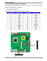
2.9.3 <DVI Display LV-67AD and LV-67AD2>
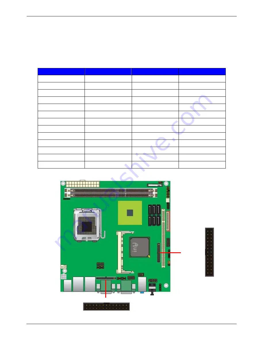
The board provides optional DVI1-D
(LV-67AD)
and two DVI
(LV-67AD2)
interfaces with
Intel Q45, compliant with DVI 1.0 standard.
Connector:
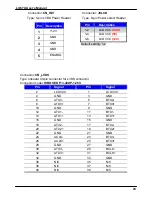
CN_DVI1, CN_DVI2
Connector type: 26-pin header connector (pitch = 2.00mm)
Pin Number
Assignment
Pin Number
Assignment
1 TX1+ 2 TX1-
3 Ground 4 Ground
5 TXC+ 6 TXC-
7 Ground 8 PVDD
9 N/C 10 N/C
11 TX2+ 12 TX2-
13 Ground 14 Ground
15 TX0+ 16 TX0-
17 N/C 18
HPDET
19 DDCDATA 20 DDCCLK
21 GND 22 N/C
23 N/C 24 N/C
25 N/C 26 N/C
CN_DVI1
1
2
25
26
1
2
25
26
CN_DVI2
Summary of Contents for LV-67A
Page 1: ...LV 67A Mini ITX motherboard User s Manual Edition 1 2 2009 06 11 ...
Page 6: ...LV 67A User s Manual 6 This Page is Left for Blank ...
Page 11: ...LV 67A User s Manual 11 1 4 Mechanical Drawing Unit inch ...
Page 37: ...LV 67A User s Manual 37 This Page is Left for Blank ...
Page 49: ...LV 67A User s Manual 49 This Page is Left for Blank ...
Page 53: ...LV 67A User s Manual 53 Appedix B System Resources B 1 I O Port Address Map ...
Page 54: ...LV 67A User s Manual 54 ...
Page 55: ...LV 67A User s Manual 55 B 2 Memory Address Map ...
Page 56: ...LV 67A User s Manual 56 B 3 System IRQ Resources ...


