


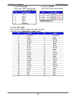


2.16 <Indicator and Switch>
The
JFRNT
provides front control panel of the board, such as power button, reset and
beeper, etc. Please check well before you connecting the cables on the chassis.
Connector:
JFRNT
Type: onboard 14-pin (2 x 7) 2.54-pitch header
Function
Signal
PIN
Signal
Function
HDLED+ 1
2
IDE LED
HDLED- 3
4 N/C
Reset+ 5
6 PWRLED-
Power
LED
Reset
Reset- 7
8 SPK+
N/C 9
10
N/C
PWRBT+ 11
12
N/C
Power
Button
PWRBT- 13
14
SPK-
Speaker
14
1
JFRNT
2
13
Summary of Contents for LV-66A
Page 1: ...LV 66A Mini ITX Motherboard User s Manual Edition 1 02 2009 02 17 ...
Page 6: ...LV 66A User s Manual 6 The Page is Left For Blank ...
Page 10: ...LV 66A User s Manual Introduction 10 1 3 Mechanical Drawing ...
Page 33: ...LV 66A User s Manual Hardware Setup 33 JCSEL2 JCSEL1 CN_COM2 ...
Page 38: ...LV 66A User s Manual 38 This Page is Left For Blank ...
Page 46: ...LV 66A User s Manual System Configuration 46 This Page is Left for Blank ...
Page 48: ...LV 66A User s Manual I O Port Pin Assignment 48 This Page is Left for Blank ...
Page 54: ...LV 66A User s Manual System Resources 54 Appendix C System Resources C1 I O Port Address Map ...
Page 55: ...LV 66A User s Manual System Resources 55 ...
Page 56: ...LV 66A User s Manual System Resources 56 C2 Memory Address Map ...
Page 57: ...LV 66A User s Manual System Resources 57 ...
Page 58: ...LV 66A User s Manual System Resources 58 C3 System IRQ Resources ...
Page 60: ...LV 66A User s Manual Programming GPIO s 60 datasheet ...
Page 62: ...LV 66A User s Manual 62 This Page is Left for Blank ...